- پروگرامرها
- دما و رطوبت
- سایر ماژول ها
- سنسور بخار سرد
- کی پد و جوی استیک
- ماژول GPS-GPRS
- ماژول رله و سوییچ
- ماژول شبکه
- ماژول نمایشگر
- ماژول های RF
- ماژول های RFID
- ماژول های پخش صدا
- ماژول های پردازش تصویر
- ماژول های تاریخ و ساعت
- ماژول های تغذیه – ولتاژ – جریان
- ماژول های ذخیره داده
- ماژول های شتاب سنج و ژیروسکوپ
- ماژول های مبدل
- ماژول های محافظ شارژ باتری
- ماژول های مولد پالس
- ماژول ولتمتر و آمپرمتر
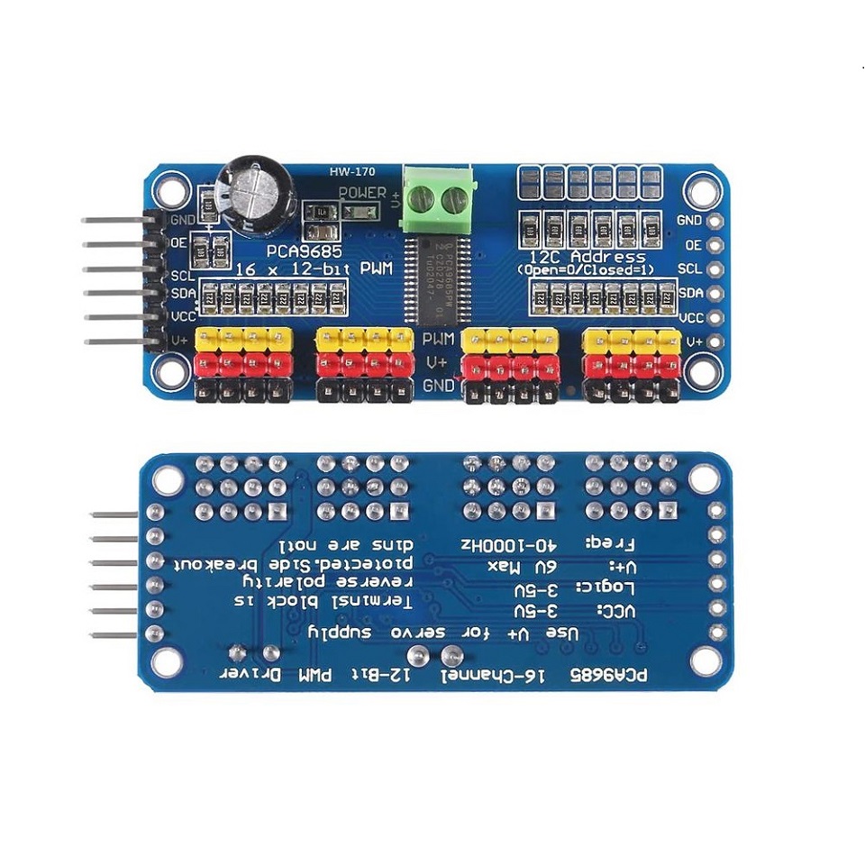
ماژول کنترل سروو موتور با آی سی PCA9685
14
نفر در حال مشاهده این محصول هستند!
دسته: درایور و کنترلر موتور
توضیحات
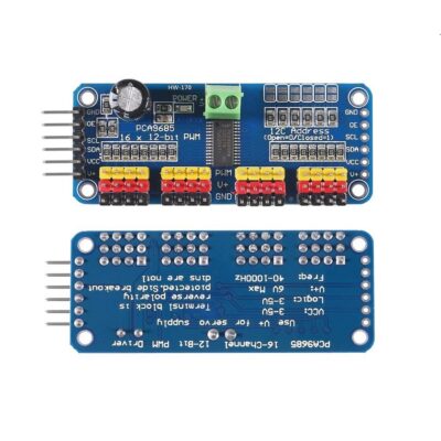
PCA9685 16 Channels PWM I2C 12-Bit
The PCA9685 16 Channel PWM I2C 12-Bit is a pulse width modulation (PWM) controller that communicates over the I2C protocol and is capable of controlling up to 16 individual PWM outputs.
Each PWM output can provide a 12-bit PWM signal.
This device is commonly used in applications where precise control of multiple PWM channels is required, such as in the control of LED lights, motors, servo motors, and other applications where intensity, speed, or position need to be varied.
SPECIFICATIONS AND FEATURES
Controller: PCA9685
Supply voltage: 5V DC
Maximum current per pin: 25 mA
Interface: I2C
Resolution: 12 bits
Number of channels: 16
Operating frequency: 40 Hz to 1000 Hz
Protection: Voltage Reversal
Dimensions: 62mm x 26mm
Weight: 12g
Datasheet
PCA9685
Servo Driver
Pinout
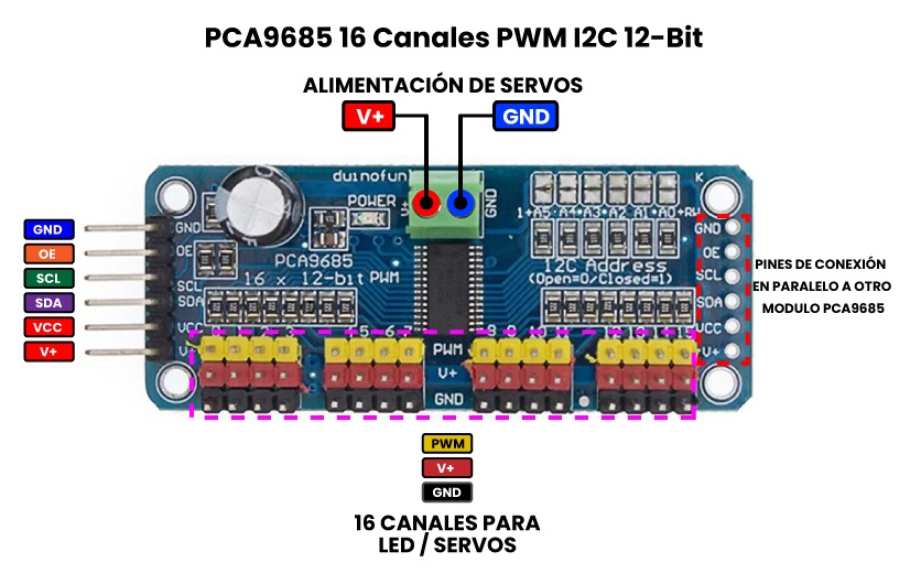
Description of the Pins
Power pins
GND : This is the power and signal ground pin, it must be connected
VCC – This is the logic power pin (3V to 5V) , connect it to the logic level you want to use for the PCA9685 output.
V+ – This is an optional power pin that will supply distributed power to the servos. If you are not using the servos, you can leave it disconnected. It is not used at all by the chip. You can also inject power from the top of the board on pin number 2. You need to provide 5V/6V DC if you are using servos. If you need to, you can go up to 12V DC, but if you mess up and connect VCC to V+, YOU COULD DAMAGE THE BOARD.
Control pins
SCL – I2C Clock Pin, connect this to the clock line of your I2C microcontroller.
SDA : I2C data pin, connect it to the data line of your I2C microcontroller.
OE – Output Enable. This can be used to quickly disable all outputs. When this pin is low , all pins are enabled . When the pin is high, the outputs are disabled . This is an optional pin.
Ports of departure
There are 16 output ports. Each port has 3 pins: V+, GND, and PWM. Each PWM runs independently, but they all need to have the same PWM frequency. I.e. for LEDs you probably want 1.0 KHz but servos need 60 Hz, so you can’t use half for LEDs at 1.0 KHz and half at 60 Hz. The maximum current per pin is 25 mA.
There are 220 ohm resistors inside the board in series with all the PWM pins and the output logic is the same as VCC, so keep this in mind if using LEDs.
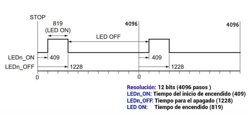
PWM duty cycle
For example; the ON time of each LED driver output and the PWM duty cycle can be controlled independently using the LEDn_ON and LEDn_OFF registers , if you set the LEDn_ON time to 409 and for LEDn_OFF to 1128, the duty cycle will be:
نظرات (0)
اولین نفری باشید که دیدگاهی را ارسال می کنید برای “ماژول کنترل سروو موتور با آی سی PCA9685”
محصولات مشابه
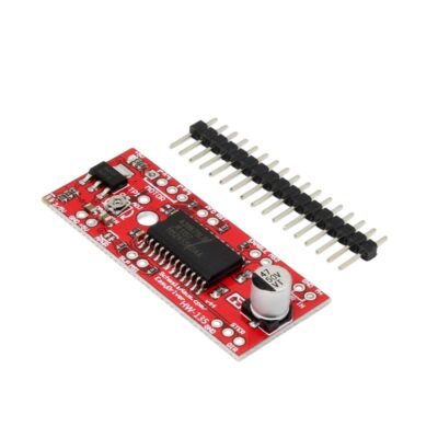
ماژول درایور استپ موتور A3967
۱۳۵,۰۰۰ تومان
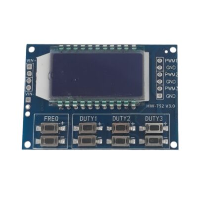
ماژول سیگنال ژنراتور PWM سه کاناله به همراه نمایشگر
۲۸۵,۰۰۰ تومان
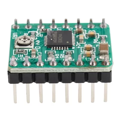
درایور استپر موتور A4988 برد سبز
۱۰۵,۰۰۰ تومان




دیدگاهها
هیچ دیدگاهی برای این محصول نوشته نشده است.