- پروگرامرها
- دما و رطوبت
- سایر ماژول ها
- سنسور بخار سرد
- کی پد و جوی استیک
- ماژول GPS-GPRS
- ماژول رله و سوییچ
- ماژول شبکه
- ماژول نمایشگر
- ماژول های RF
- ماژول های RFID
- ماژول های پخش صدا
- ماژول های پردازش تصویر
- ماژول های تاریخ و ساعت
- ماژول های تغذیه – ولتاژ – جریان
- ماژول های ذخیره داده
- ماژول های شتاب سنج و ژیروسکوپ
- ماژول های مبدل
- ماژول های محافظ شارژ باتری
- ماژول های مولد پالس
- ماژول ولتمتر و آمپرمتر
جاباتری SMD سکه ای CR2032 CR2025 CR2016
۱۵,۰۰۰ تومان
ماژول مبدل آنالوگ به دیجیتال 16 بیتی ADS1115
۲۳۳,۰۰۰ تومان
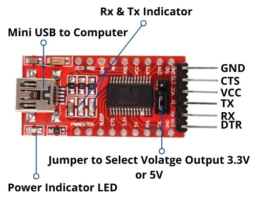
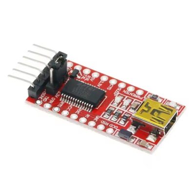
ماژول مبدل USB به سریال FT232
۱۴۵,۰۰۰ تومان
موجود در انبار
30
نفر در حال مشاهده این محصول هستند!
دسته: ماژول ها, ماژول های مبدل
توضیحات
Features
Supports Mac, Linux, Android, WinCE, Windows 7/8/8.1/10…
3 power mode : 5V output, 3.3V output, or powered by target board (3.3V-5V)
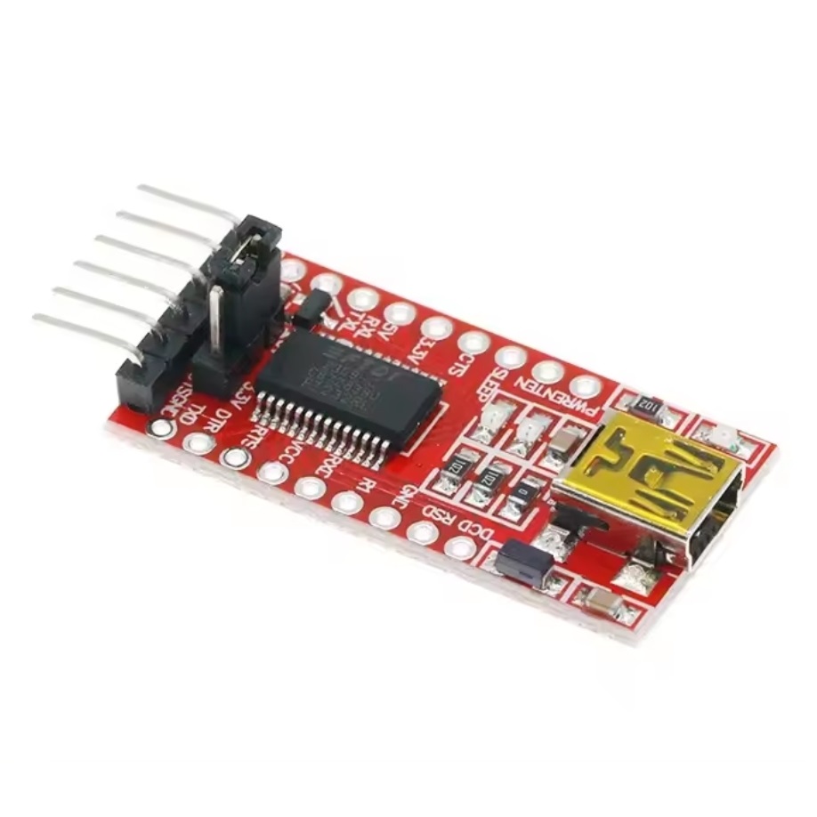
3 LEDs: TXD LED, RXD LED, POWER LED
Functional Pins
TXD, RXD, RTS#, CTS# : connected to the onboard soldered pin headers
The other Pins : accessable on the drill holes (separate pin headers are also provided for easily connecting to user system, the pitch is compatible with bread boards)
How to Use
In the case of working with a MCU:
VCCIO ↔ 3.3V or 5V output (the module is powered from USB, onboard jumper should be shorted to 3.3V or 5V)
GND ↔ GND
TXD ↔ MCU.RX (signal direction: MCU.RX << FT232 << PC.TX)
RXD ↔ MCU.TX (signal direction: MCU.TX >> FT232 >> PC.RX)
RTS ↔ MCU.CTS (signal direction: MCU.CTS << FT232 << PC.RTS)
CTS ↔ MCU.RTS (signal direction: MCU.RTS >> FT232 >> PC.CTS)
Install the Drivers
Most Linux distributions include drivers for the FTDI FT232R.
However, this is not the case in any of the versions of Windows.
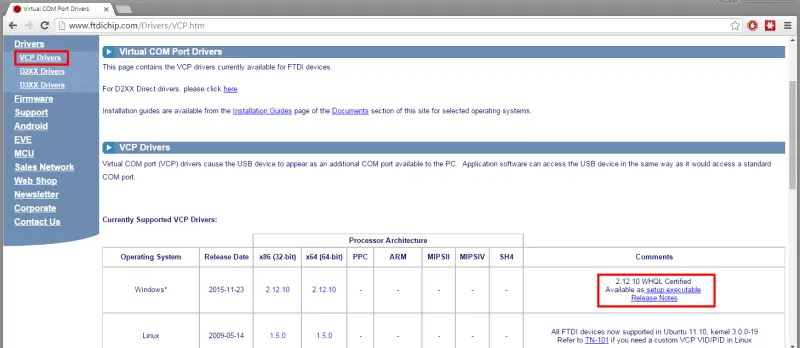
Fortunately, in case of using a Windows operating system (or a Linux distribution that does not include the drivers) the solution is as simple as downloading and installing the drivers from the manufacturer’s website.
Here we select VPC Drivers (Virtual COM Ports) and select the most current driver available.
In the case of Windows, make sure to download the executable installer, instead of the compressed file, since the installation is easier.
After installing the driver, we connected the FTDI FT232R.
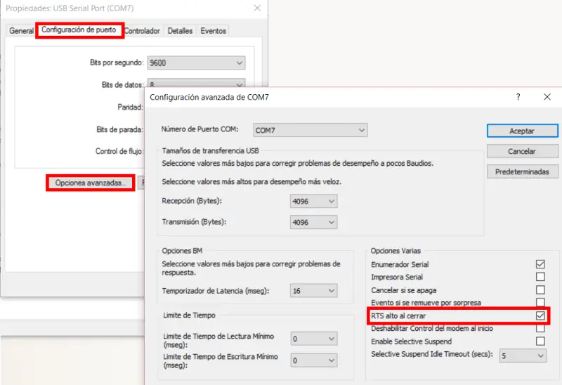
We go to devices, and in COM ports we locate the one corresponding to the FTDI FT232R. Right-click and choose “Properties”

Here, in advanced options we activate the option “High RST on closing”.
This will reset the Arduino when loading the program, which is necessary for the Arduino programming process.
نظرات (0)
اولین نفری باشید که دیدگاهی را ارسال می کنید برای “ماژول مبدل USB به سریال FT232”
محصولات مشابه
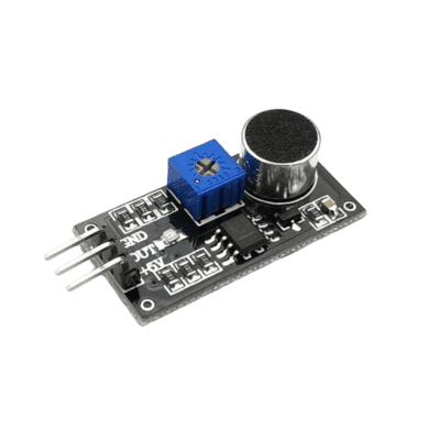
ماژول میکروفون دیجیتال با چیپ LM393
۷۱,۰۰۰ تومان
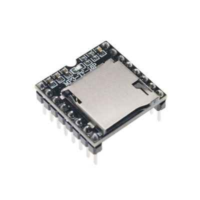
ماژول پخش فایل های صوتی DF PLAYER
۱۳۵,۰۰۰ تومان
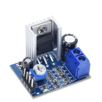
ماژول آمپلی فایر مونو 18 وات TDA2030
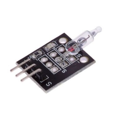
ماژول سوئیچ جیوه ای
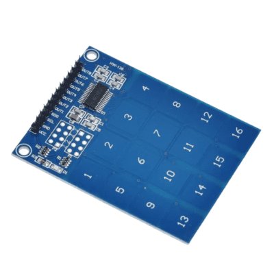
ماژول کی پد 4 در 4 لمسی TTP229
۱۱۰,۰۰۰ تومان
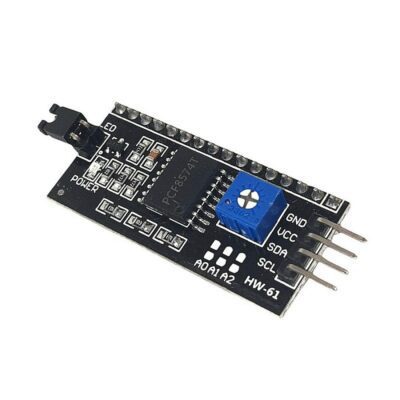
ماژول راه انداز lcd 2×16 با ارتباط i2c چیپ PCF8574
۷۰,۰۰۰ تومان
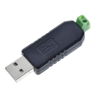
مبدل USB به سریال RS485
۱۱۵,۰۰۰ تومان



دیدگاهها
هیچ دیدگاهی برای این محصول نوشته نشده است.