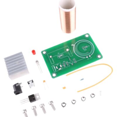
PARTS LIST
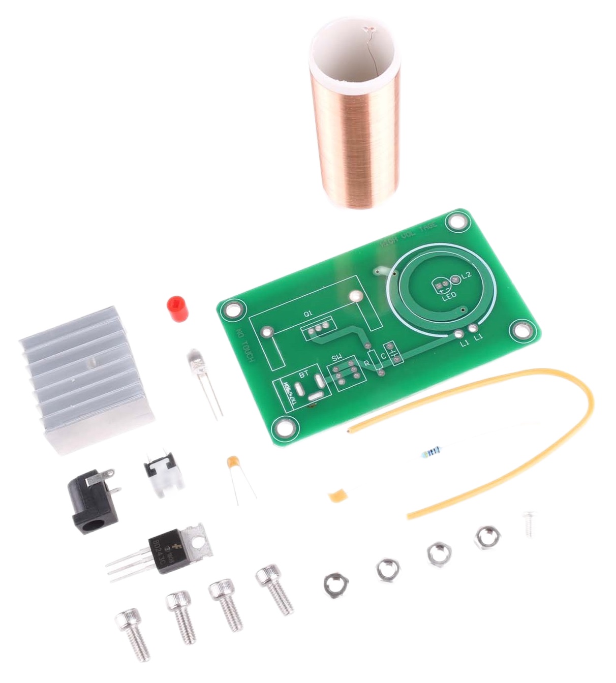
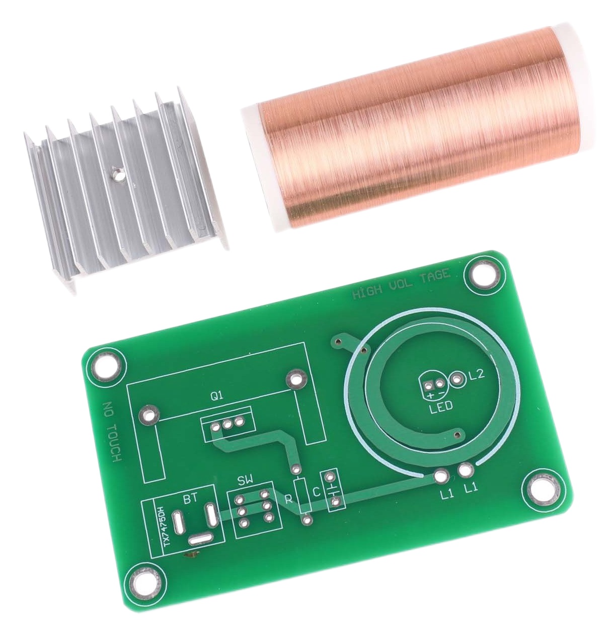
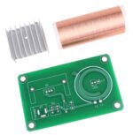
1 x circuit board
1 x 47K ohm resistor
1 x 10⁴ monolithic capacitor 1 x BD243C transistor
1 x heatsink
1 x 2.1mm dc power jack
1 x pushbutton
1 x red switch cap
1 x LED
1 x copper pillar
1 x hook-up wire
1 x screw for heatsink
4 x hex head bolts
4 x nuts
1 x neon lamp
Requires at least 12 Vdc 400 ma power supply,
INSTRUCTIONS
STEP 1) Solder the 47K resistor (R) into board.
STEP 2) Solder the 104 monolithic capacitor (C) into board.
STEP 3) Attach the transistor, BD2432C, to the heatsink using a screw and nut.
Fasten securely, so that the heat from the transistor will transfer to the heatsink.
If available, spread a thin layer of heatsink compound or thermal grease between the transistor and heatsink before fastening.
Insert the heatsink and transistor into the board and solder in place.
STEP 4) Solder 2.1mm power jack (BT) into board.
STEP 5) Solder pushbutton (SW) into board. Install red switch cap on pushbutton.
STEP 6) Locate the long lead of the LED. This is the positive (+) side of the LED. Insert and solder (LED) to board.
Be sure to pay attention to the polarity marked on the board (ignore the LED symbol).
STEP 7) Solder and attach copper pillar (secondary coil). The coil wire has an enamel insulating coating.
Before soldering coil wire, the enamel must be re-moved or “stripped” from end being soldered.
This can be done by sanding with sandpaper or scraping the enamel with a knife.
Insert and solder into board (L2). Copper pillar can be attached to board by applying any quick-dry adhesive to bot-tom of pillar where it attaches to board.
Locate long wire lead on copper pillar. Arrange lead in vertical position (arc producing end).
Be careful not to touch this wire while operating.
STEP 8) Prepare primary coil by stripping 1/8” of the insulation from both ends.
Insert and solder one end into board (L1).
Route wire around copper pillar in a circular shape (make sure wire does not touch copper pillar) and solder other end of wire into board (L1).
STEP 9) Install the hex bolts and nuts in the corners of the board, as supports.
STEP 10) Plug in 12Vdc power supply with 2.1mm/2.5mm power plug.
Note: DO NOT TOUCH COPPER COIL LEAD WHILE OPERATING.
Also, avoid touching the heatsink.
It gets hot while the device is operating.
For additional fun, remotely light up the included neon lamp by holding it near the arc of the coil.



دیدگاهها
هیچ دیدگاهی برای این محصول نوشته نشده است.