- پروگرامرها
- دما و رطوبت
- سایر ماژول ها
- سنسور بخار سرد
- کی پد و جوی استیک
- ماژول GPS-GPRS
- ماژول رله و سوییچ
- ماژول شبکه
- ماژول نمایشگر
- ماژول های RF
- ماژول های RFID
- ماژول های پخش صدا
- ماژول های پردازش تصویر
- ماژول های تاریخ و ساعت
- ماژول های تغذیه – ولتاژ – جریان
- ماژول های ذخیره داده
- ماژول های شتاب سنج و ژیروسکوپ
- ماژول های مبدل
- ماژول های محافظ شارژ باتری
- ماژول های مولد پالس
- ماژول ولتمتر و آمپرمتر
مینی برد بورد MINI BREADBOARD
۶۵,۰۰۰ تومان
موجود در انبار
30
نفر در حال مشاهده این محصول هستند!
دسته: برد بورد, قطعات الکترونیکی
توضیحات
Features
Completely reusable.
Colored coordinates for easy component placement.
Phosphor bronze nickel plated spring clips.
Terminal Strip, Tie-point 300.
Distribution strip, Tie-point 100.
Pitch: 2.54mm
Color: White
Material: ABS Plastic
Size: 85mm x 55mm
What is a breadboard?
A breadboard is a solderless device for temporary prototype with electronics and test circuit designs.
Most electronic components in electronic circuits can be interconnected by inserting their leads or terminals into the holes and then making connections through wires where appropriate.
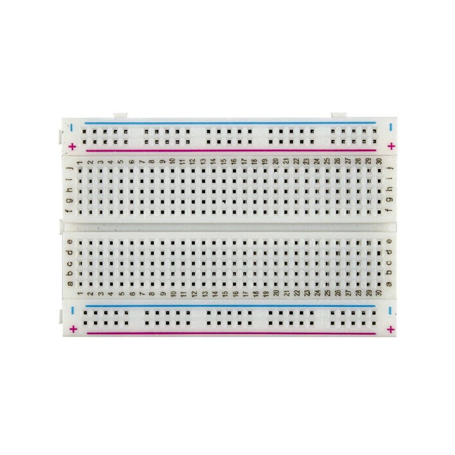
The breadboard has strips of metal underneath the board and connect the holes on the top of the board.
Note that the top and bottom rows of holes are connected horizontally and split in the middle while the remaining holes are connected vertically.
Internal Connections

Note that the top and bottom rows of holes are connected horizontally and split in the middle while the remaining holes are connected vertically.
How to use a Breadboard?
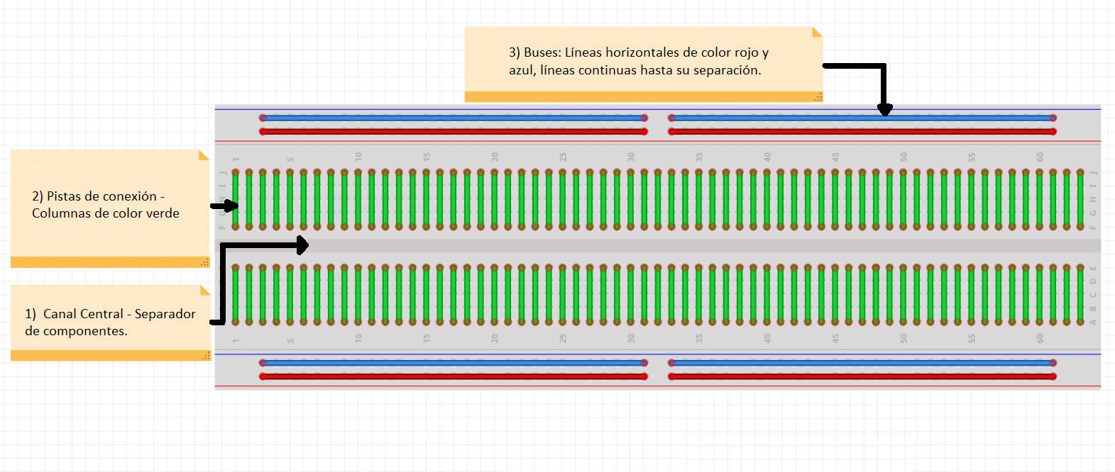
A breadboard is divided into 3 regions
1.Central channel
It is the region located in the middle of the breadboard, it is used to properly place integrated circuits.
2.Buses
The buses are located at both ends of the Breadboard, they are represented by the red lines (positive or voltage buses) and blue (negative or ground buses) and they drive according to these, there is no physical connection between them. The power supply is usually connected here.
3.Connection tracks
The tracks are located in the central part of the Breadboard, here you can connect your circuit considering that they are vertical columns in a linear manner.
Errors when connecting components to a breadboard
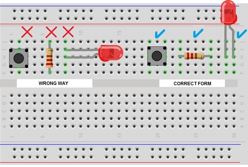
The typical mistake when connecting a component to the Breadboard is to connect it to a single vertical connection track, this is wrong and will short the component so each pin has to be connected to a different connection track.
The following image shows the correct and incorrect way to insert components into a breadboard
