- پروگرامرها
- دما و رطوبت
- سایر ماژول ها
- سنسور بخار سرد
- کی پد و جوی استیک
- ماژول GPS-GPRS
- ماژول رله و سوییچ
- ماژول شبکه
- ماژول نمایشگر
- ماژول های RF
- ماژول های RFID
- ماژول های پخش صدا
- ماژول های پردازش تصویر
- ماژول های تاریخ و ساعت
- ماژول های تغذیه – ولتاژ – جریان
- ماژول های ذخیره داده
- ماژول های شتاب سنج و ژیروسکوپ
- ماژول های مبدل
- ماژول های محافظ شارژ باتری
- ماژول های مولد پالس
- ماژول ولتمتر و آمپرمتر
ماژول اندازه گيري جريان 30 آمپر ACS712
11
نفر در حال مشاهده این محصول هستند!
توضیحات
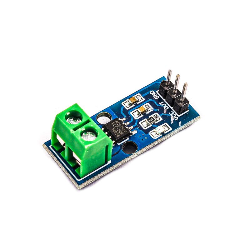
The 30A range Current Sensor Module ACS712 consists of a precise, low-offset, linear Hall circuit with a copper conduction path located near the surface of the die.
Applied current flowing through this copper conduction path generates a magnetic field in which the Hall IC converts into a proportional voltage.
Sensing and controlling current flow is a fundamental requirement in a wide variety of applications including, over-current protection circuits, battery chargers, switching mode power supplies, digital watt meters, programmable current sources, etc.
This ACS721 current module is based on the ACS712 sensor, which can accurately detect AC or DC current.
The maximum AC or DC that can be detected can reach 30A, and the present current signal can be read via analog I / O port of Arduino.
Note
ACS712 is based on the principle of the Hall test.
Features
Low-noise analog signal path
Device bandwidth is set via the new FILTER pin
5 µs output rise time in response to step input current
Small footprint, low-profile SOIC8 package
2.1 kVRMS minimum isolation voltage from pins 1-4 to pins 5-8
5.0 V, single supply operation
66 to 185 mV/A output sensitivity
Output voltage proportional to AC or DC currents
Factory-trimmed for accuracy
Extremely stable output offset voltage
Nearly zero magnetic hysteresis
The ratiometric output from the supply voltage.
Supply Voltage: 4.5V~5.5V DC
Measure Current Range: 30A
Sensitivity: 100mV/A
Package Includes
1 x 30A Range Current Sensor Module ACS712.
Step 1
Making the connections
The ACS712 is a Hall effect based sensor, where the applied current (either AC or DC) flowing through this copper conduction track generates a magnetic field which is detected by the integrated Hall IC and converted into a voltage.
DC voltage that goes from 0 V – 5 V that can be obtained from its “OUT” terminal.
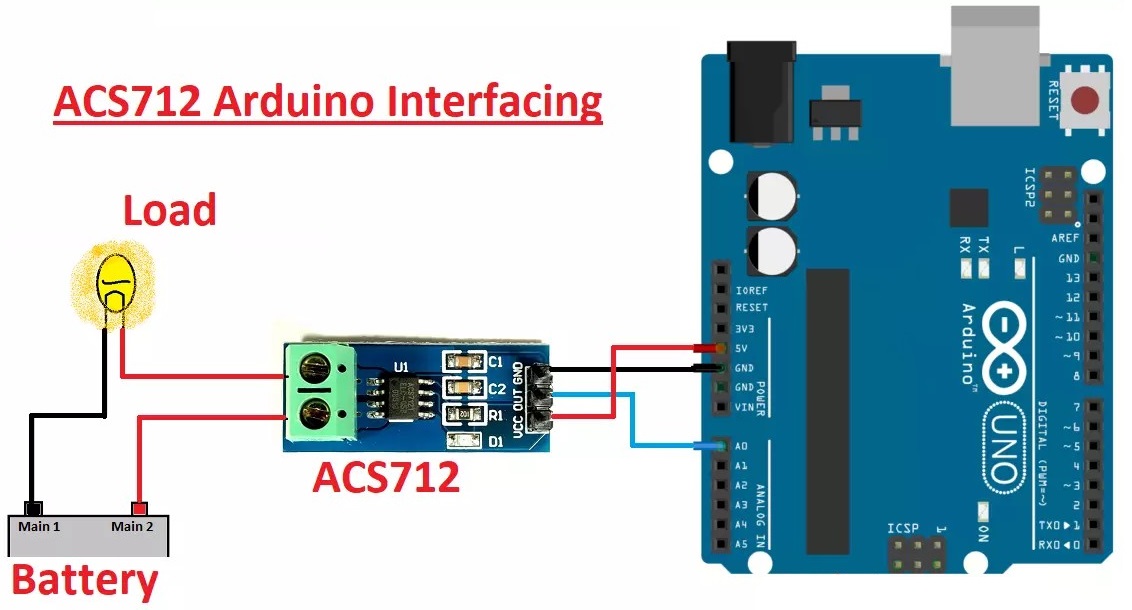
Step 2
Loading the Code
The sensor ideally gives us a value of 2.5 V for a current of 0 A and from there it increases proportionally depending on the sensitivity, maintaining a linear relationship between the sensor output voltage and the current.
a) Code for Direct Current “DC”
The following example code converts the sensor data coming through analog input A0 into the current value corresponding to the measurement.
/* Code to measure CD */
float S ensibility=0.066;   /* in (V/A) According to the specifications of this model */

void  setup () {
 Serial.begin (9600);
/* We establish serial communication at 9600 baud */
}

void  loop () {
 /* get the average current of 200 samples */
  float I=get_current(200);
  Serial.print (" Stream: ");
  Serial.println (I,3);
  delay (100);
}

float get_current( int n_samples)
{
  float voltageSensor;
  float V0 = 2,460; //voltage at OUT when the current to be measured is 0A (varies from device to device)
  float current=0;
  for( int i=0;i<n_samples;i++)
  {
   voltageSensor = analogRead (A0) * (5.0 / 1023.0); //sensor reading
   current=current+(Sensorvoltage-V0)/Sensitivity; //Equation to obtain the current
  }
current=current/n_samples;
return (stream);
}
It is important to remember that in most cases it is necessary to calibrate the sensor.
b) Code for Alternating Current “AC”
/* Code to measure AC */
 float S ensibility=0.066; /* According to the specifications of this model */
 float  offset=0.100;  //We look for it to be an approximate value of the noise amplitude
 floatNetworkvoltage =  127.0; //Common in Mexico but adjustment is necessary
void setup () {
 Serial.begin (9600);


 /* We establish serial communication at 9600 baud */
}

void  loop ()  {
  float  Ip=get_stream(); /* we obtain the peak current */  float Irms=Ip*0.707; //RMS Intensity = Ipeak/(2^1/2) float P=Irms*NetworkVoltage; // P=IV watts //Serial.print("Ip: ");   //Serial.print(Ip,3);


  //Serial.print("A, Power: ");
  //Serial.print(P,3);
  //Serial.print("W");
  Serial.print (" Irms: ");
  Serial.print (Irms,3);
  Serial.println ( " A " );
  delay (500);
}

float  get_current()
{
  floatSensorVoltage  ;
  float  current=0;
  long  time = millis ();
  float Imax=0;
  float Imin=0;
  float V0 = 2,460; //voltage at OUT when the current to be measured is 0A (varies from device to device)
  while ( millis ()-time<500) //we perform measurements for 0.5 seconds
{
  voltageSensor = analogRead (A0) * (5.0 / 1023.0); //sensor reading
   /* to reduce the noise a little we apply a low pass filter, which is similar to averaging 10 samples*/
  current=0.9*current+0.1*((Sensorvoltage-V0)/Sensitivity); //Equation to obtain the current
  if (current>Imax)Imax=current;
  if (current<Imin)Imin=current;
  }
return((( Imax-Imin)/2)-offset );
}
نظرات (0)
اولین نفری باشید که دیدگاهی را ارسال می کنید برای “ماژول اندازه گيري جريان 30 آمپر ACS712”
محصولات مشابه
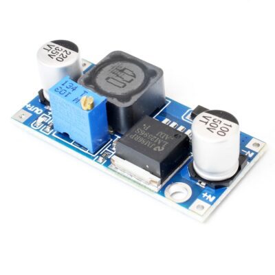
ماژول کاهنده LM2596 حداکثر جریان خروجی 3 آمپر
۷۸,۰۰۰ تومان
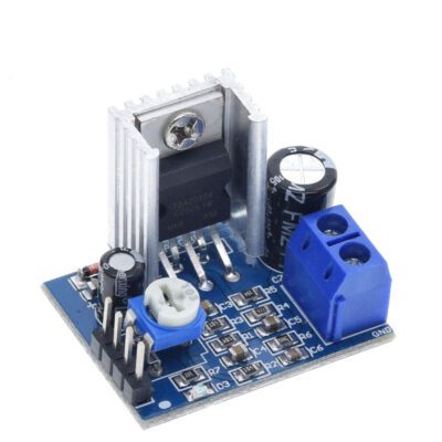
ماژول آمپلی فایر مونو 18 وات TDA2030
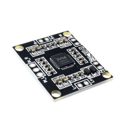
ماژول آمپلی فایر 2X10W کلاس D با تراشه PAM8610
۱۱۵,۰۰۰ تومان
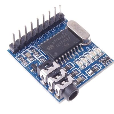
ماژول MT8870 دریافت کدهایDTMF
۹۰,۰۰۰ تومان



دیدگاهها
هیچ دیدگاهی برای این محصول نوشته نشده است.