- پروگرامرها
- دما و رطوبت
- سایر ماژول ها
- سنسور بخار سرد
- کی پد و جوی استیک
- ماژول GPS-GPRS
- ماژول رله و سوییچ
- ماژول شبکه
- ماژول نمایشگر
- ماژول های RF
- ماژول های RFID
- ماژول های پخش صدا
- ماژول های پردازش تصویر
- ماژول های تاریخ و ساعت
- ماژول های تغذیه – ولتاژ – جریان
- ماژول های ذخیره داده
- ماژول های شتاب سنج و ژیروسکوپ
- ماژول های مبدل
- ماژول های محافظ شارژ باتری
- ماژول های مولد پالس
- ماژول ولتمتر و آمپرمتر
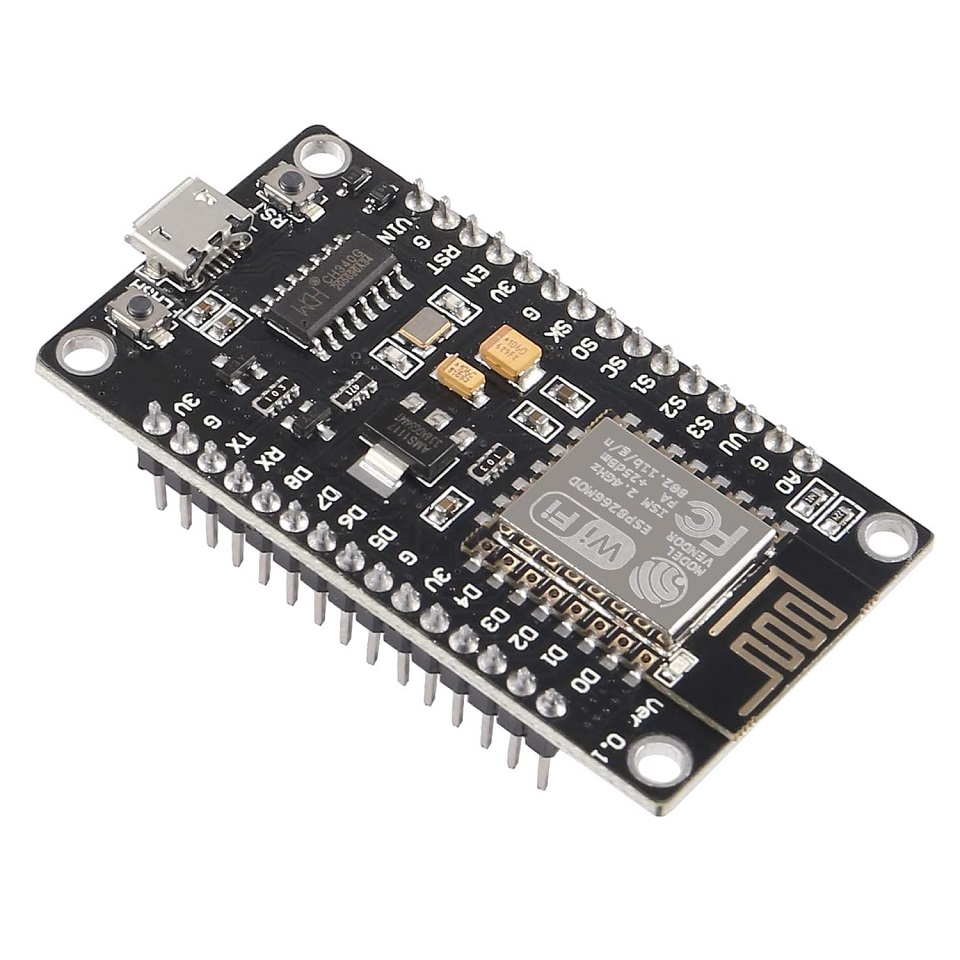
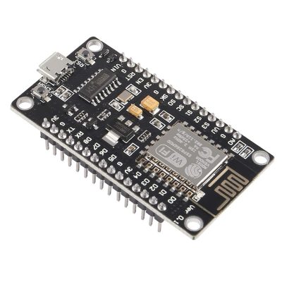
برد توسعه NodeMCU V3 دارای هسته وایفای ESP8266 و مبدل CH340C
26
نفر در حال مشاهده این محصول هستند!
دسته: ESP8266, بردهای توسعه, میکروکنترلرها
توضیحات
NodeMcu WIFI Board Based on ESP8266 CH340 Module
Description
NodeMCU
It is a board similar to Arduino, the difference is that the Nodemecu is aimed at Internet of Things (IoT) solutions, which has an ESP8266 chip which is used to connect sensors and actuators to the Internet via WIFI.
Each of the boards has the ESP6266 Microcontroller (ESP-12E) with 802.11 bgn WLAN.
They are used to develop and create prototypes of the Internet of Things “IOT” quickly, easily and at a low cost.
They are also designed to connect to a breadboard and thus create a functional prototype.
The programming is very simple, you can use the Lua-Script or Arduino-IDE development environments.
The NodeMCU integrates a powerful ESP6266 Microcontroller (ESP-12E) with a 32-bit architecture, which is more powerful than some Arduino boards and has WIFI connectivity and you can create an AP access point.
Each Nodemcu from the factory comes with a Pre-Installed Firmware which allows you to work with the interpreted language LUA by sending commands through the serial port.
ESP8266
ESP8266 is a serial port to WiFi bridge, it includes a microcontroller to manage the TCP/IP protocol and the necessary software for the 802.11 connection, most models have digital inputs/outputs (I/O) and some models have an analog input Like other microcontrollers, its strong point is having WIFI access and due to its low price, the ESP8266 chip seems destined to give a big push to what has been called the Internet of Things.
SPECIFICATION AND FEATURES
Power Voltage (USB): 5V DC
Input/Output Voltage: 3.3V DC
SoC: ESP8266 (ESP-12E Module)
Supply Voltage (VIN): 5V
USB driver: CH340C chip
CPU: Tensilica Xtensa LX3 (32 bit)
Clock Frequency: 80MHz/160MHz
RAM: 32KB
SRAM: 64KB
External Flash Memory: 4MB
Wi-Fi 2.4 GHz, 802.11 b/g/n
Operation modes: STA/AP/STA+AP
Security mechanism: WPA/WPA2
Has LM1117 regulator with 3.3V 500mA output
Size: 31×59 mm
How to install the ch340 driver to program the NodeMCU
To start using this Rectangular NodeMCU board and programming it from the PC or Laptop you must install its driver, in this case the board incorporates the CH340 chip which is responsible for programming and establishing USB-Serial communication.
In the following link you can download the CH341SER universal controller which includes the CH340 version that the board needs
CH340 Controller
Note
Install the driver according to the operating system of your PC or Laptop.
If you have installed it previously, do not install the driver.
Once the driver is installed, you can connect the board to your PC.
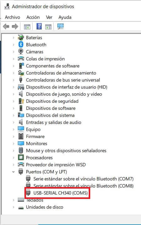
To verify that the driver was installed correctly and a COM port was assigned to the board, follow the following steps:
Open “Device Manager”
Connect the board to the PC
Click on Ports (COM, LPT)
You should recognize the plate as shown in the following image
How to program NodeMCU
Once the controller is installed, you can program it in different programming environments, you can choose:
Arduino IDE (in C++ language),
MicroPython
Javascript (Espruino, Duktape, Mongoose JS)
And others…
It is commonly used with the Arduino IDE as it has a wide variety of examples, information and other resources that will help you start using this board. To use with Arduino IDE you must perform the following steps:
Open Arduino IDE.
If you have not installed it, download it directly from the Arduino page , install the executable version, not install the portable version.
Copy the following URL: http://arduino.esp8266.com/stable/package_esp8266com_index.json
Go to the Arduino tab called “File”.
Click on “Preferences”.
Go to the Additional Card URL Manager:
In the box paste the URL.
If there is another URL, place a comma at the end, give a space and paste the URL.
Click Ok.
Go to the Arduino tab called “Tools”
Click on “Plate:” and then “Card Manager…”
Sandra a window, look for the “esp8266 by ESP8266 Community” plates and install them.
To check the installation of the esp8266 cards in Arduino IDE and upload codes to the board, do the following:
Go to the Arduino tab called “Tools”
Click on “Plate:”
Select ESP8266 Boards Arduino and look for the board “NodeMCU 1.0 (ESP-12E Module)”
Then connect the board to the PC.
Go to “ Tools” again and select the COM port that the PC assigned to the board.
Load the following code to check that everything went well.
The code is a blink on the LED on the board that is assigned to pin 2 of the ESP.
Blink Code – Hello world in NodeMCU:
void setup () {
// initialize digital pin 2 as output
pinMode (2, OUTPUT );
}
void loop () {
digitalWrite (2, HIGH ); // Turn on the LED
delay (1000); // Wait one second
digitalWrite (2, LOW ); // Turn off the LED
delay (1000); // Wait a second
}
Note
If the program does not load directly to the board you will have to put the board in programming mode before loading the code.
To put it in programming mode, do the following
Press the “FASH” button when the code is already being uploaded. When the upload process begins, stop pressing the button, you will have to carry out this process every time you upload a sketch to the NodeMCU.
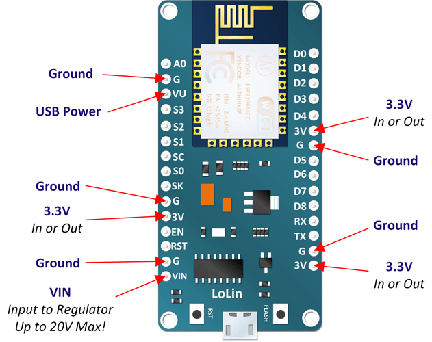
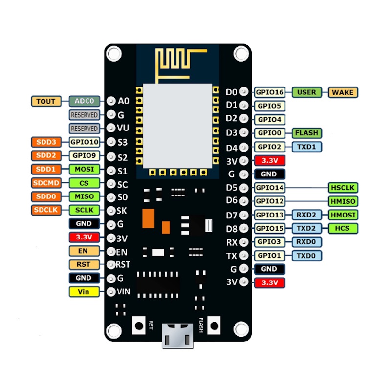
نظرات (0)
اولین نفری باشید که دیدگاهی را ارسال می کنید برای “برد توسعه NodeMCU V3 دارای هسته وایفای ESP8266 و مبدل CH340C”
محصولات مشابه
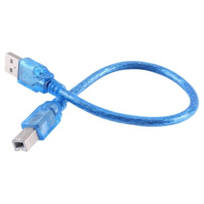
کابل USB پرينتر 30 سانتیمتر مناسب برای پروگرام بردهای آردوینو
۷۵,۰۰۰ تومان
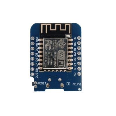
ماژول WeMos D1 Mini دارای هسته وایفای ESP8266 و پورت میکرو USB جهت پروگرام
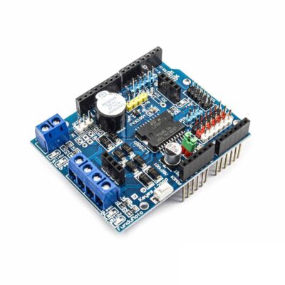
شیلد موتور درایور L298P آردوینو دارای بازر
۴۸۵,۰۰۰ تومان




دیدگاهها
هیچ دیدگاهی برای این محصول نوشته نشده است.