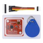
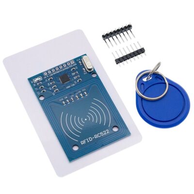
ماژول PN532 NFC RFID V3 با قابلیت خواندن و نوشتن
PN532 RFID NFC Reading and Writing Module V3
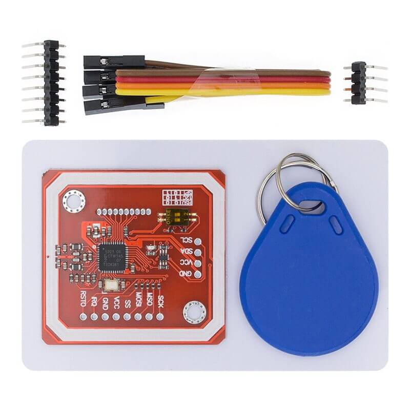
The Pn532 RFID/NFC module is an electronic device that allows you to read and write to tags, communicate with phones that support NFC and even act as an RFID/NFC tag.
If you want to evaluate the PN532, or conduct research and development in the field of NFC or RFID, this card is ideal for that application.
It is ideal for quickly developing RFID/NFC applications with Arduino or Raspberry Pi.
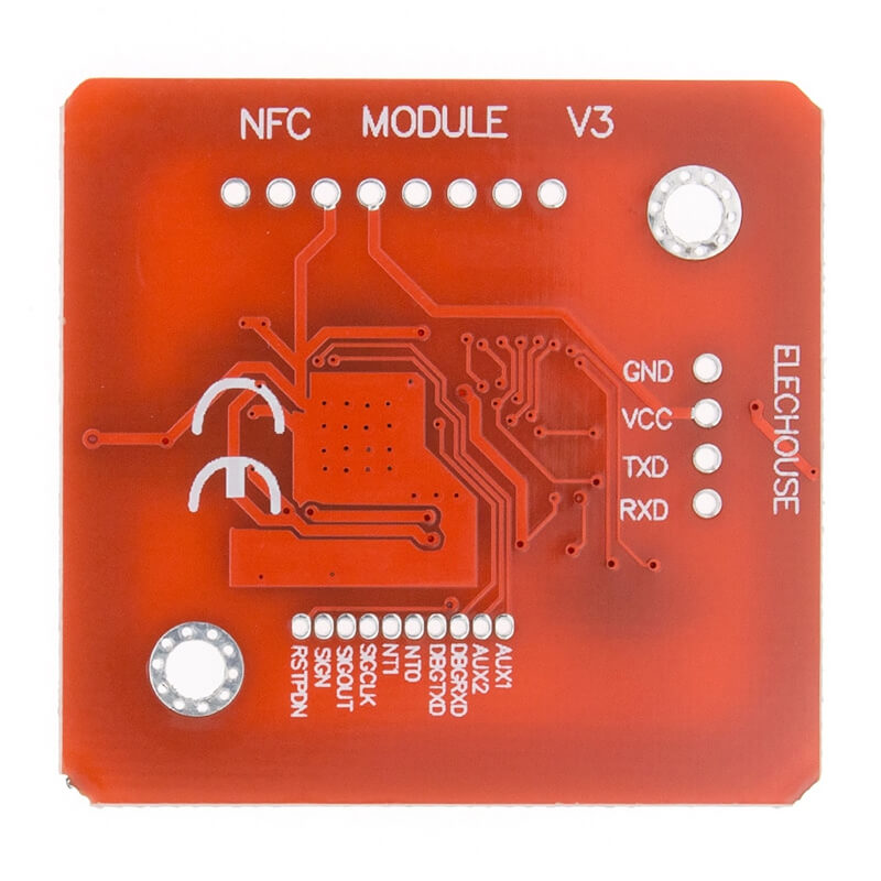
It has 3 communication interfaces to use with other microcontrollers.
It is worth mentioning that it is very flexible and allows communication with microcontrollers through UART at 3.3V, I2C or SPI, you just have to correctly configure the DIP-SWITCH according to the communication interface you want to use.
The chip is well supported by libnfc (a library for developing NFC applications).
Another option is to directly connect a USB-Serial cable to the UART of this card to start working with the PN532 on your PC.
Applications of RFID
security systems
Identification of the user, car or product…
Smart houses
Information Technology
Intelligent systems
RFID in construction: tracking tool, pipe tracking
RFID in hospital and health care
RFID payment systems
Time and presence
SPECIFICATIONS AND FEATURES
Type: NFC RFID Module Kit
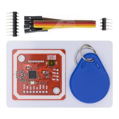
Includes: PN532 Module, white Mifare 1k S50 RFID Card and keychain type Mifare 1k RFID TAG
Operating voltage: 3.3V to 5V
Operating frequency: 13.56 MHz
Communication interface: SPI, I2C, High-speed UART (HSU)
Data transfer: Max. 10Mbit/s
Compatible with standard: RFID ISO/IEC 14443-A and NFC: ISO/IEC 18092
Supported card types: Mifare 1K S50, Mifare S701, Mifare Ultralight, Mifare Pro, Mifare DESFire, Mifare Classic.
Dimensions: 41x43mm
How to connect PN532 module to Arduino UNO?
In the following tutorial we will focus on the PN532 Module and you will learn the communication modes, types of protocols it supports, how to connect to the different Arduino boards and how to program it easily with the elechouse library for PN532.
The PN532 module has 3 communication interfaces which are the following:
1. SPI (Serial Peripheral Interface)
2. I2C (Serial Communication Port)
3. High-speed UART (HSU)
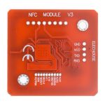
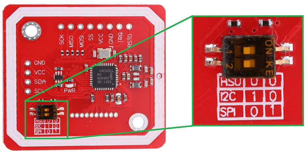
The module has a DIP-SWITCH which will allow you to select the communication interface, whether UART, I2C or SPI, you just have to follow the table that comes on the pcb to configure it correctly.
Connection with Arduino boards
Connect the PN532 module with the Arduino development boards in its 3 communication interfaces.
we let you the following image, which defines the communication pins for each Arduino board.
For other cards or microcontrollers, consult the pinout and identify their communication interfaces.
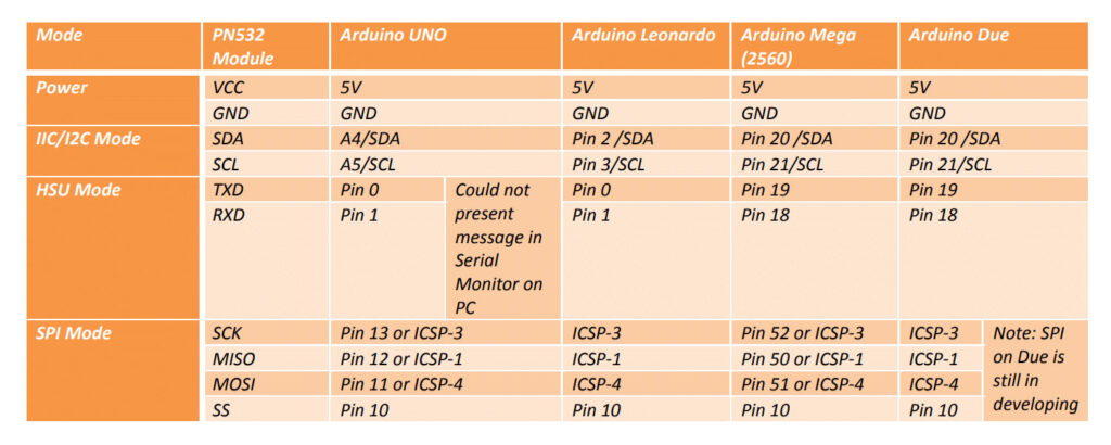
In this tutorial we will use an Arduino Uno to connect the PN532 module.
below you will have 3 images which detail the connection diagram between these two devices.
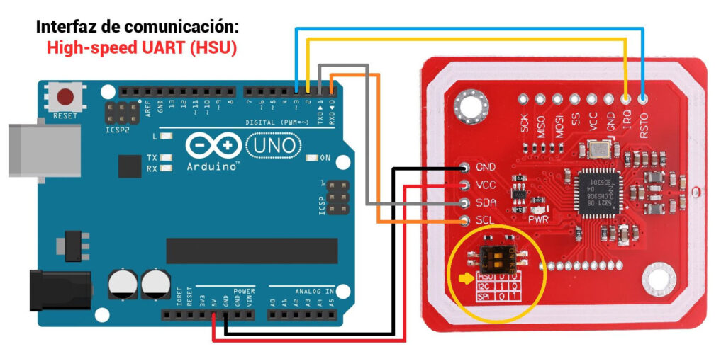
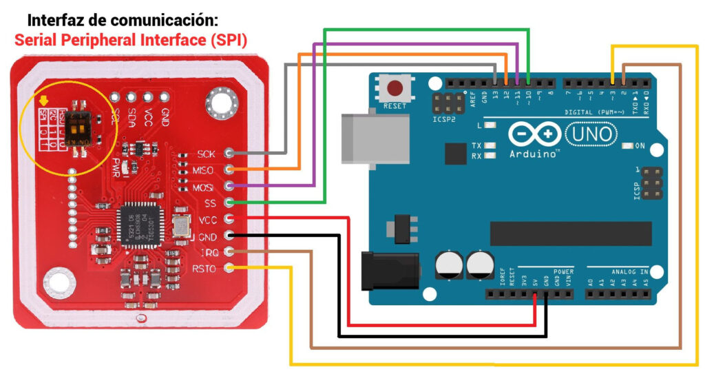
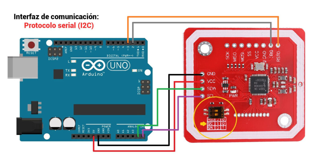
PN532 module programming with the Arduino IDE
To program the PN532 we will use the library developed by Adafruit, download by clicking Here.
This library only allows working with I2C and SPI communication, but not UART.
Now that you have downloaded the library, open your Arduino IDE and import the library in its .zip format.
The example will be used that allows us to show the data of the PN532 reader and the tags that are brought close to the module, we will use 12C communication, so we will connect the PN532 module as shown in the image “Connection for I2C in Arduino UNO” that we mentioned previously, verify that channel 1 of the DIP-SWITCH is in a high state and channel 2 is in a low state.
Next connect your Arduino to your PC, then copy and paste the following code which is modified to work with the I2C configuration.
//  Test code coming soon
#include <Wire.h>
#include <SPI.h>

#include <Adafruit_PN532.h>
#define PN532_IRQ (2)
#define PN532_RESET (3)

// Interfaz de comunicación por I2C
Adafruit_PN532 nfc(PN532_IRQ, PN532_RESET);
void setup(void) {

 Serial.begin(115200);
 nfc.begin();

 uint32_t versiondata = nfc.getFirmwareVersion();

if (! versiondata) {
    Serial.print("PN53x no encontrado");
    while (1);
  }

  // Mostrar datos del sensor
  Serial.print("Encontró el chip PN5"); Serial.println((versiondata>>24) & 0xFF, HEX);
  Serial.print("Firmware ver. "); Serial.print((versiondata>>16) & 0xFF, DEC);
  Serial.print('.'); Serial.println((versiondata>>8) & 0xFF, DEC);

  // Configurar para leer etiquetas RFID
  nfc.setPassiveActivationRetries(0xFF);
  nfc.SAMConfig();

  Serial.println("Esperando tarjeta ISO14443A");
}

// Funcion auxiliar para mostrar el buffer
void printArray(byte *buffer, byte bufferSize) {
   for (byte i = 0; i < bufferSize; i++) {
      Serial.print(buffer[i] < 0x10 ? " 0" : " ");
      Serial.print(buffer[i], HEX);
   }
}

void loop(void) {
  boolean success;
  uint8_t uid[] = { 0, 0, 0, 0, 0, 0, 0 };
  uint8_t uidLength;

  success = nfc.readPassiveTargetID(PN532_MIFARE_ISO14443A, &uid[0], &uidLength);

  if (success) {
    Serial.println("Tarjeta encontrada");
    Serial.print("UID Longitud: ");
    Serial.print(uidLength, DEC);Serial.println(" bytes");
    Serial.print("UID: "); printArray(uid, uidLength);
    Serial.println("");

    delay(1000);
  }
  else
  {
    Serial.println("Tarjeta no encontrada");
  }
}
Upload the code to your Arduino Uno and open the serial monitor, change the baud rate to “115200” and select the “New line” option.
How does PN532 RFID module work?
The PN532 includes an 80C51 processor with 40 KB ROM and 1 KB RAM, along with the necessary elements to properly operate NFC communication.
Supports 6 modes of operation
ISO/IEC 14443A/MIFARE
Reader/Writer, MIFARE Classic 1K Card and MIFARE Classic 4K Card
Reader/Writer ISO/IEC 14443B
FeliCa Reader/Writer and Card emulation
ECMA 340 Peer-to-Peer ISO/IEC 18092
The typical actuation distance is 50mm for reading and writing, and 100mm for emulation.
The reading speed is up to 212 kbits/s and the writing speed is up to 424 kbits/s.
These values depend, among others, on the antenna integrated into the module.
The PN532 operates at 3.3V but supports supply voltages from 2.7V to 5.4V.
I2C/UART communication lines operate at 3.3V to 24V TTL.
However, the SPI interface works at 3.3, but incorporates 100 Ohm resistors in series so that it can also be connected to 5V.
Consumption is 100mA in Stand-By mode and 120mA during reading and writing. Additionally, it has two low energy modes, a Soft-Power-Down mode with a consumption of 22uA, and a Hard-Power-Down mode with a consumption of 1uA.
Likewise, it can be used with computers and microcomputers such as Raspberry Pi with the libnfc library.

