MT8870 DTMF Decoder Module
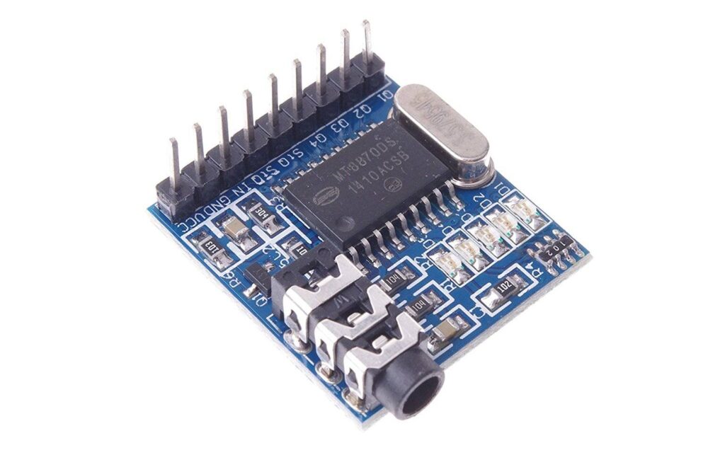
MT8870 DTMF Decoder Module is a very tiny module that is based on MT8870 DTMF decoder ic.
The module offers a 3.5mm audio connector to connect an audio source.
The DTMF Signal in the audio source is decoded and the digital outputs on the module, indicate the key pressed.
You may connect a phone to the module and the module will output the key(0-9, *, #, A, B, C or D)pressed on the audio source.
This module is suitable for modem interfaces, mobile radios and other DTMF related applications.
Can be used to build mobile controlled robots, home automation projects, IVR style applications, etc
This component is ideally suited to adding dual tone multi-frequency (DTMF) decoding to your project.
This detection module interprets the incoming tone and produces a coded output that can be connected to all manner of microcontrollers.
The MT8870 Tone Decoder is a kind of commonly used multi-frequency decode IC product developed by the MITEL company.
It is a complete DTMF receiver.
After it received the DTMF signal, it will divide the signal into high-frequency group and low-frequency group and send the signal to the digital decoder which can figure out the key value then send it to the outside Bus via four lines( Q1, Q2, Q3, Q4) as the binary form.
Features
• Onboard MT8870 complex frequency decoding chip
• Onboard voice input interface
• Onboard 5 LED indicator, easy to view the output status
• The basic chip has been the main pin leads
• PCB size: 26.5 (mm) x 24.5 (mm)
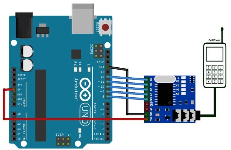
MT8870 Interfacing diagram
DTMF decoder modules can be interfaced with any kind of microcontroller like PIC, Arduino, etc.
It requires 4 digital I/O pins to be interfaced with the 4 binary bit output pins.
It also requires a 5 volt supply to the power of the module.
In the below diagram, a simple interfacing example is shown where a generic microcontroller unit is shown.

Application
1. Wired Robot control via mobile phone keypad.
2. Home Automation
3. Security Systems
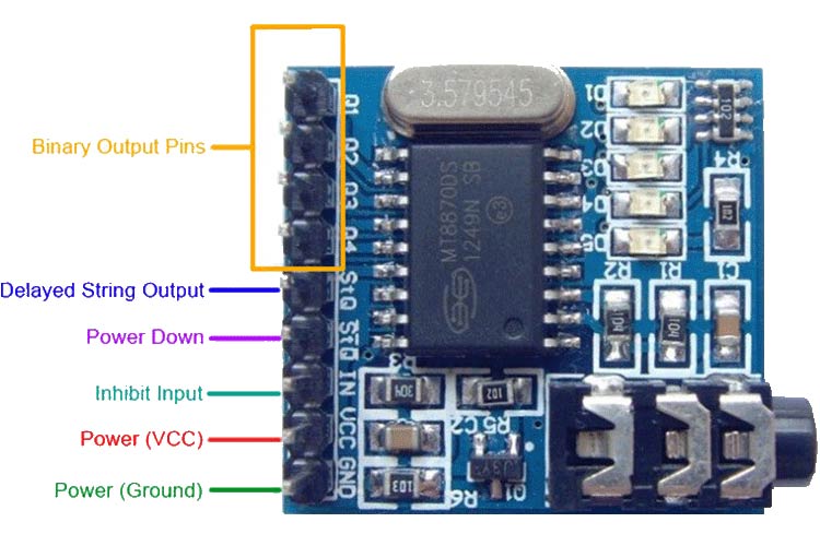
MT8870 DTMF Decoder Module Pinout Description
| Comments | Function | Pin Name |
| Binary Bit 1 | Q1 | |
| Binary Bit 2 | Q2 | |
| Binary Bit 3 | Q3 | |
| Binary Bit 4 | Q4 | |
| Represents Binary Bit 0 | Delayed String Output | StQ |
| Power Down Input | StQ | |
| Logic high inhibits the detection of tones representing characters A, B, C and D | Inhibit Input | IN |
| 4.5V – 5.5V (5.0V Nominal) | DC Supply Input | VCC |
| Ground | GND |

