- پروگرامرها
- دما و رطوبت
- سایر ماژول ها
- سنسور بخار سرد
- کی پد و جوی استیک
- ماژول GPS-GPRS
- ماژول رله و سوییچ
- ماژول شبکه
- ماژول نمایشگر
- ماژول های RF
- ماژول های RFID
- ماژول های پخش صدا
- ماژول های پردازش تصویر
- ماژول های تاریخ و ساعت
- ماژول های تغذیه – ولتاژ – جریان
- ماژول های ذخیره داده
- ماژول های شتاب سنج و ژیروسکوپ
- ماژول های مبدل
- ماژول های محافظ شارژ باتری
- ماژول های مولد پالس
- ماژول ولتمتر و آمپرمتر
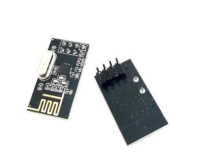
ماژول گیرنده و فرستنده رادیویی NRF24L01
۷۰,۰۰۰ تومان
موجود در انبار
26
نفر در حال مشاهده این محصول هستند!
دسته: مخابرات, وای فای WiFi
توضیحات
NRF24L01 is a single-chip radio transceiver that uses the 2.4 – 2.5 GHz ISM band world-wide.
Transceiver means the same module can be used as a transmitter or receiver. Power consumption of the module is very low, only 9.0mA at an output power of -6dBm and 12.3mA in RX mode which is even less than a LED.
Its maximum range is up to 100 meters if used in an open space with an antenna.
Application
• Wireless mouse, keyboard, joystick
• Keyless entry
• Wireless data communication
• Surveillance
• Alarm and security systems
• Home automation
• Automotive
• Telemetry
• Intelligent sports equipment
• Industrial sensors
• Toys
NRF24L01 pinout and specifications are given below.
NOTE: Don’t connect the VCC pin directly to the 5V pin of Arduino. Use a 3.3 V regulator.
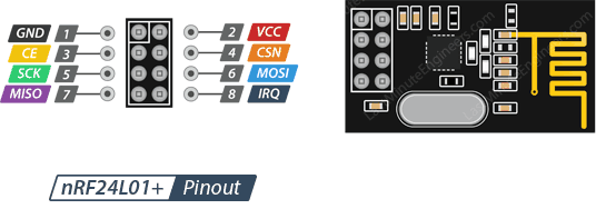 PINOUT
GND is the ground pin. It is marked with a square to identify it from the other pins.
VCC supplies power to the module. It can be anywhere from 1.9 to 3.9 volts. You can connect it to the 3.3V output from your Arduino.
Remember that connecting this to the 5V pin will probably destroy your nRF24L01+ module!
CE (Chip Enable) is an active-high pin. When selected, the nRF24L01 will either transmit or receive, depending on which mode it is currently in.
CSN (Chip Select Not) is an active-low pin and is normally kept HIGH. When this pin goes low, the nRF24L01 starts listening on its SPI port for data and processes it accordingly.
SCK (Serial Clock) accepts clock pulses provided by the SPI bus master.
MOSI (Master Out Slave In) is the SPI input to the nRF24L01.
MISO (Master In Slave Out) is the SPI output from the nRF24L01.
IRQ is an interrupt pin that can alert the master when new data is available to process.
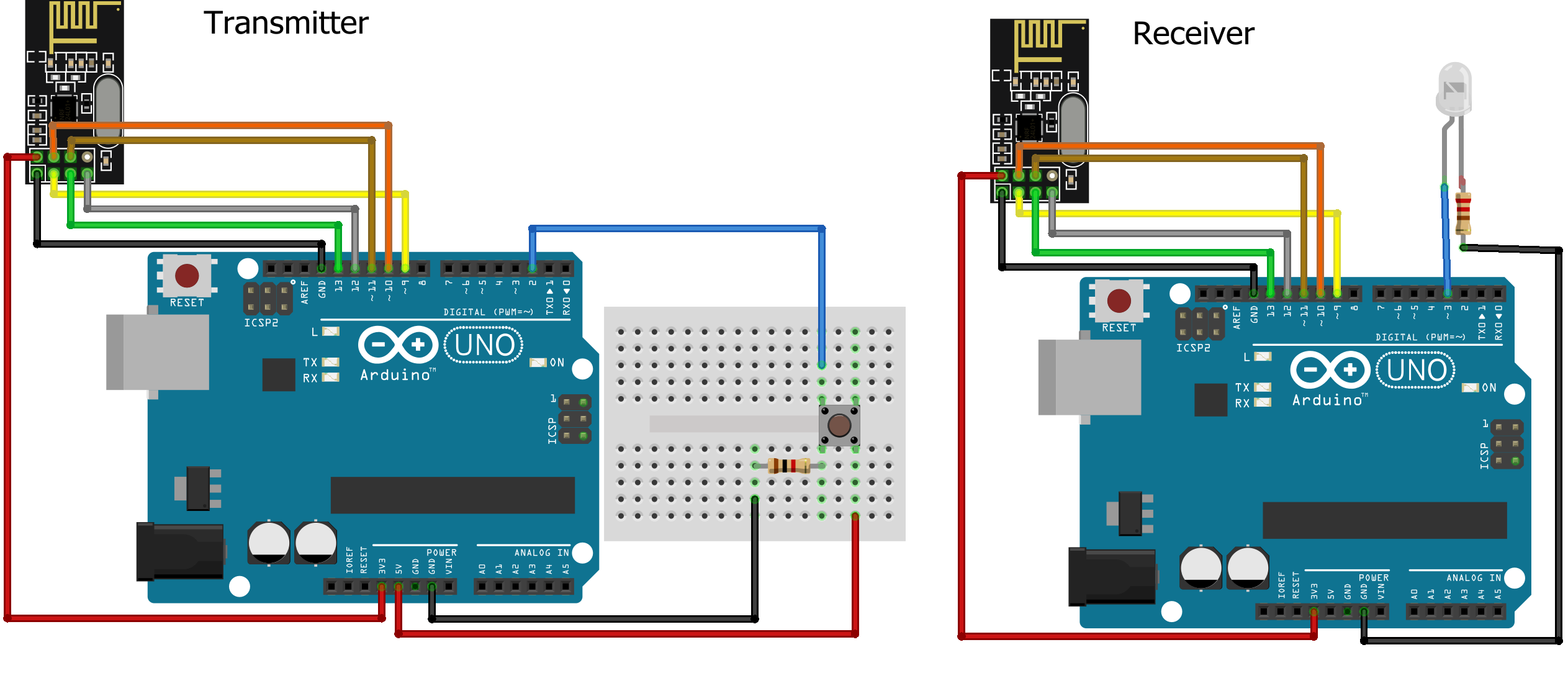
نظرات (0)
اولین نفری باشید که دیدگاهی را ارسال می کنید برای “ماژول گیرنده و فرستنده رادیویی NRF24L01”
محصولات مشابه
ریموت و گیرنده 4 کاناله PT2272 دارای فرکانس 315MHZ
کابل UFL to SMA-F 15cm – مبدل IPX به SMA
۵۵,۰۰۰ تومان




دیدگاهها
هیچ دیدگاهی برای این محصول نوشته نشده است.