- پروگرامرها
- دما و رطوبت
- سایر ماژول ها
- سنسور بخار سرد
- کی پد و جوی استیک
- ماژول GPS-GPRS
- ماژول رله و سوییچ
- ماژول شبکه
- ماژول نمایشگر
- ماژول های RF
- ماژول های RFID
- ماژول های پخش صدا
- ماژول های پردازش تصویر
- ماژول های تاریخ و ساعت
- ماژول های تغذیه – ولتاژ – جریان
- ماژول های ذخیره داده
- ماژول های شتاب سنج و ژیروسکوپ
- ماژول های مبدل
- ماژول های محافظ شارژ باتری
- ماژول های مولد پالس
- ماژول ولتمتر و آمپرمتر
ماسفت IRFZ34
۱۵,۰۰۰ تومان

ماژول مولد سیگنال SI5351 CLOCK SIGNAL GENERATOR I2C
۲۰۵,۰۰۰ تومان
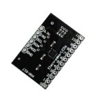
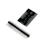
ماژول سنسور خازنی لمسی MPR121 I2C Touch Keyboard
15
نفر در حال مشاهده این محصول هستند!
دسته: کی پد و جوی استیک, ماژول ها
توضیحات
MPR121 I2C Touch Keyboard
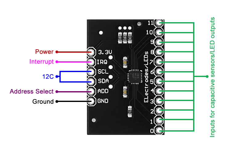
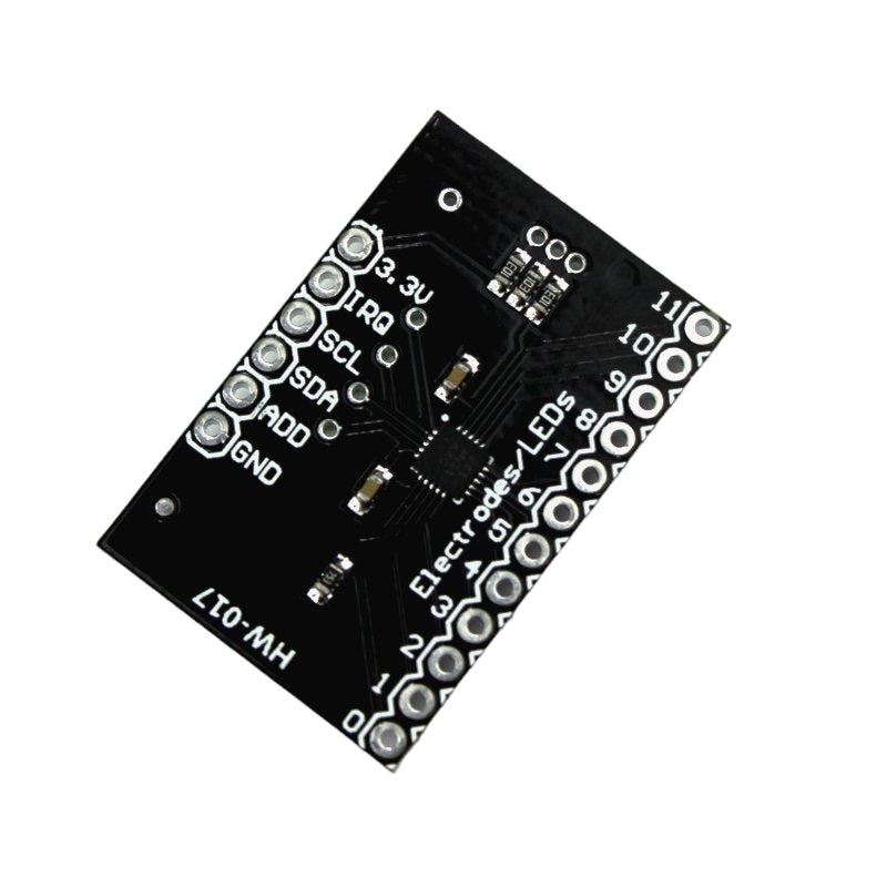
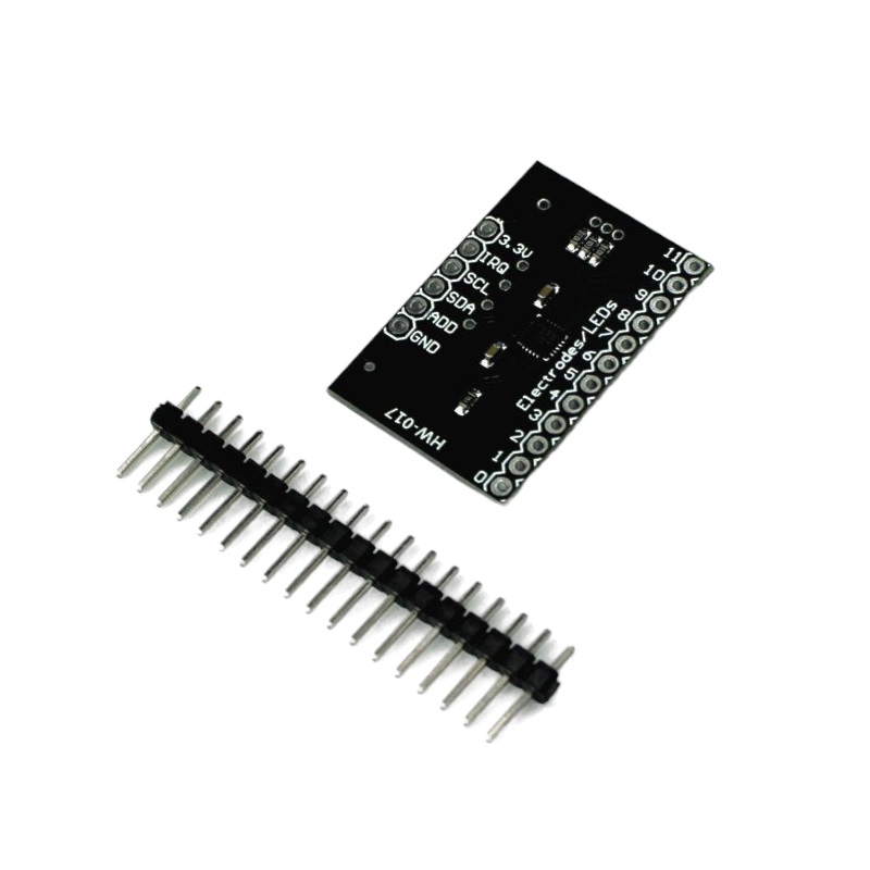
The MPR121 Touch Keypad is a capacitive touch sensor controller controlled by an I2C interface.
The chip can control up to twelve individual electrodes, as well as a simulated thirteenth. The MPR121 touch keypad also features eight LED driving pins, meaning that when these pins are not configured as electrodes, they can be used to control LEDs.
application
capacitive sensing, switch replacement, touch buttons, touch wheel, touchpad or proximity sensor.
SPECIFICATION AND FEATURES
Operating voltage: 2.5V to 3.6V
Interface: I2C
Default I2C address: 0x5A
Dimensions: 30mm x 20mm
Number of touch electrodes: 12 and 1 simulated
Number of LEDs you can control: 8
Datasheet: MPR121
Applications
Computer peripherals
MP3 players
Remote controls
Lighting controls
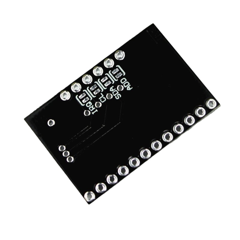
Configuration Jumper
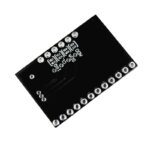
There are four jumpers on the bottom of the PCB, which are set by default (close). An addressed jumper links the ADD pin to ground, meaning the chip’s default I2C address will be 0x5A. If you need to change the address of the chip (shorting ADD to a different pin), be sure to open the jumper first. The jumpers also include SDA, SCL and the interrupt pin for 10k pull-up resistors. If you don’t need the pull-up resistors, you can open the jumpers by cutting the trace accordingly.
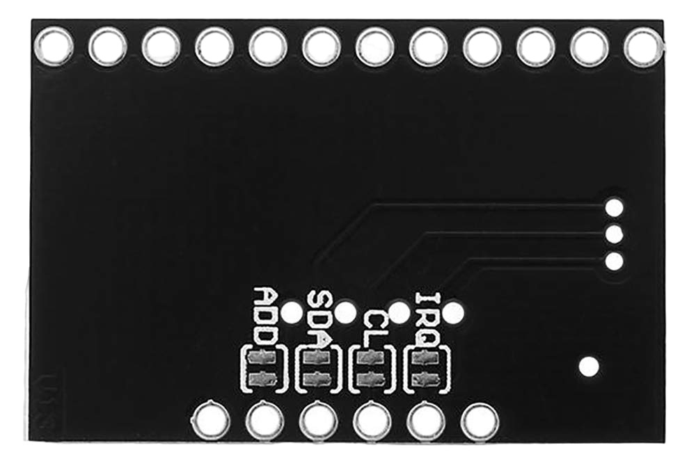
There is no regulation on the board, so the supplied voltage must be between 2.5 and 3.6 VDC. The VREG pin is connected to ground via a 0.1uF capacitor, which means that unless you modify the board, you cannot operate the MPR121 in low supply voltage mode (1.71-2.75 VDC).
MPR121 CAPACITIVE TOUCH SENSOR TUTORIAL
This tutorial will show the code needed to use the MPR121 module, explain its features, operation and a basic example to start using it.
The MPR121 module can control 12 electrodes, each electrode behaves as a capacitive touch sensor, the communication is with an I2C interface, so it only uses two pins and is easy to implement with any microcontroller.
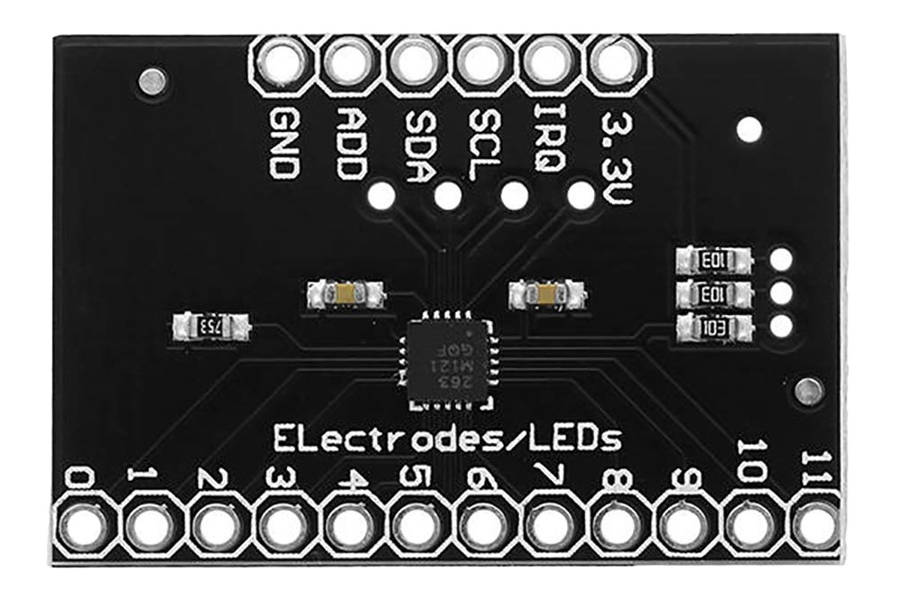
On the back of the MPR121 module there are 4 jumpers, which must be broken if you do not need to use the pullup resistors that the module has.
You can also break the ADD jumper to change the address in case you need to connect another MPR121 to the I2C bus.

The electrode can be any conductive surface, such as metal, metallic paper, copper; To activate the electrode there does not necessarily have to be contact, the sensitivity depends on how it is calibrated, this is done with thresholds which the module uses as a reference to consider Touch or not. An activation threshold is assigned to each electrode.
If not all the electrodes are used, they can also be configured as outputs to activate LEDs
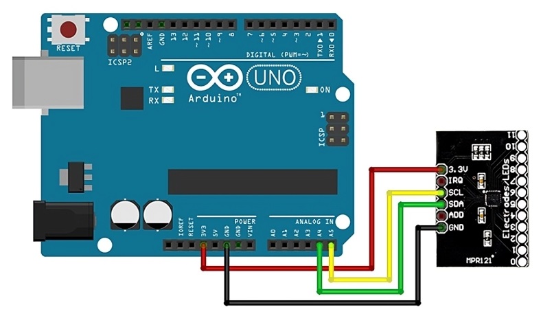
Connections between the MPR121 module and Arduino
The power supply is 3.3V, communication is through the I2C of the Arduino whose pins vary depending on the board used, the IRQ pin generally goes to an external interruption pin that the Arduino has, below is the connection of the MPR121
| MPR121 | Arduino Uno, Nano, Mini Pro | Arduino Mega 2560 | Arduino Due |
|---|---|---|---|
| 3.3V | Pin 3.3V (*) | Pin 3.3V (*) | Pin 3.3V (*) |
| IRQ | Pin 2 (**) | Pin 2 (**) | Pin 2 (**) |
| SCL | Pin A5 | Pin 21 | Pin 21 |
| SDA | Pin A4 | Pin 20 | Pin 20 |
| GND | GND pin | GND pin | GND pin |
*The PMR121 module does not have an internal voltage regulator, so the Arduino’s 3.3V voltage output is used, but an external source can be used as long as it does not exceed the 3.3V voltage.
**Any digital pin can be used for the IRQ pin, in this case no interrupt is used, but if necessary, connect to the corresponding external interrupt pin.
MPR121 Programming
We will work on programming without using libraries, this way you can migrate the code to any other platform or microcontroller, such as microchip PICs.
We start by declaring the library for I2C communication and the IRQ pin.
#include < Wire .h >
 int   Pin_IRQ = 2;   // IRQ pin on digital pin 2
boolean PreviousState[12]; //To store the last state of the touch value
int address_mpr=0x5A; //address of our MPR121
Note that we also created a variable to save the previous states of the electrodes, to later see if they have changed state. In addition, a variable is declared to specify the i2C address of our PMR121 module.
The next step is to configure all our peripherals: the pins, serial communication, the i2c bus and configure the MPR121 module.
void  setup (){
   pinMode (Pin_IRQ, INPUT );
   digitalWrite (Pin_IRQ, HIGH ); //Enable the pullup resistor
  Serial . begin (9600);
   Wire . begin ();
  mpr121_Config(address_mpr);
}
As seen to configure the module we use the function mpr121_Config(address_mpr), this function is shown below:
void mpr121_Config( int address){
set_register(address,0x5E,0x00); //ELE_CFG
// Section A - Controls filtering when data is > baseline.
set_register(address, 0x2B, 0x01); //MHD_R
set_register(address, 0x2C, 0x01); //NHD_R
set_register(address, 0x2D, 0x00); //NCL_R
set_register(address, 0x2E, 0x00); //FDL_R
// Section B - Controls filtering when data is < baseline.
set_register(address, 0x2F, 0x01); //MHD_F
set_register(address, 0x30, 0x01); //NHD_F
set_register(address, 0x31, 0xFF); //NCL_F
set_register(address, 0x32, 0x02); //FDL_F
  // Section C - Sets touch and release thresholds for each electrode
  int umbral_Touch=0x44;
   int threshold_Release=0x40;

  set_register(address, 0x41, threshold_touch);  //Touch Threshold 0
  set_register(address, 0x42, threshold_Release);  //Release Threshold 0

  set_register(address, 0x43, threshold_touch);  //Touch Threshold 1
  set_register(address, 0x44, threshold_Release);  //Threshold Release 1
set_register(0x5A, 0x45, touch_threshold); //Touch Threshold 2
set_register(0x5A, 0x46, threshold_Release); //Umbral Release 2
set_register(address, 0x47, threshold_Touch); //Threshold Touch 3
set_register(address, 0x48, threshold_Release); //Release Threshold 3
set_register(address, 0x49, threshold_touch); //Threshold Touch 4
set_register(address, 0x4A, threshold_Release); //Umbral Release 4
set_register(address, 0x4B, threshold_touch); //Threshold Touch 5
set_register(address, 0x4C, threshold_Release); //Umbral Release 5
set_register(address, 0x4D, threshold_touch); //Threshold Touch 6
set_register(address, 0x4E, threshold_Release); //Umbral Release 6
set_register(address, 0x4F, threshold_touch); //Threshold Touch 7
set_register(address, 0x50, threshold_Release); //Umbral Release 7
set_register(address, 0x51, threshold_Touch); //Threshold Touch 8
set_register(address, 0x52, threshold_Release); //Release Threshold 8
set_register(address, 0x53, threshold_touch); //Threshold Touch 9
set_register(address, 0x54, threshold_Release); //Umbral Release 9
set_register(address, 0x55, threshold_Touch); //Touch threshold 10
set_register(address, 0x56, threshold_Release); //Release Threshold 10
set_register(address, 0x57, threshold_Touch); //Threshold Touch 11
set_register(address, 0x58, threshold_Release); //Release Threshold 11
// Section D
// Set the Filter Configuration
// Set ESI2
set_register(address, 0x5D, 0x04); //FIL_CFG
// Section E
// Electrode Configuration
// Set ELE_CFG to 0x00 to return to standby mode
set_register(address, 0x5E, 0x0C); //ELE_CFG Enables all 12 Electrodes
}
Basically, in the previous function, the registers necessary for its operation are configured, twelve of the registers are used to establish the “touch” thresholds and another twelve for the “release” thresholds, these register values must be increased or decreased accordingly. Depending on the type of electrode we use, we have created two variables to establish the Touch and Release thresholds of the 12 electrodes equally, but you can calibrate it independently if you use different electrodes
// Section C - Sets touch and release thresholds for each electrode int umbral_Touch=0x44; int threshold_Release=0x40; set_register(address, 0x41, threshold_touch); //Touch Threshold 0 set_register(address, 0x42, threshold_Release); //Release Threshold 0 set_register(address, 0x43, threshold_touch); //Touch Threshold 1 set_register(address, 0x44, threshold_Release); //Threshold Release 1
Both thresholds are generally close values, but it is possible to work with a hysteresis loop if the Release threshold is set below the Touch threshold.
Once the MPR121 module is configured, the next step is to read if any electrode has been pressed or touched. To do this, we use the IRQ pin, which is set to 0 every time there is a change in any of the electrodes.
After detecting the change through the IRQ pin, we read the state of the electrodes, as follows:
    if (! digitalRead (Pin_IRQ)){

      // We read the states of the electrodes of the MPR121
      Wire . requestFrom (address_mpr,2);

      byte LSB = Wire . read ();
       byte MSB = Wire . read ();

      uint16_t touched = ((MSB << 8) | LSB);  // 12 of the 16 bits correspond to touch states
As can be seen, the value of the electrodes is stored in a 16-bit variable, of which the 12 least significant bits store the values of the state of the electrodes.
The next step is to analyze the state of each of them individually, the current state is compared with the previous state and if there is any change, the corresponding action is taken, which in our case is simply notifying through the serial port.
      for ( int i=0; i < 12; i++)
      {
        boolean CurrentState= bitRead (touched, i);
         if (!(PreviousState[i])&&CurrentState)
        {
              Serial . print ( " Electrode " );
               Serial . print ( i );
               Serial . println ( " just touched " );
        }

        if (PreviousState[i]&&(!CurrentState))
        {
              Serial . print ( " Electrode " );
               Serial . print ( i );
               Serial . println ( " is no longer being touched " );
        }
        PreviousState[i]=CurrentState;
      }
Below is the full code to read all 12 electrodes.
#include < Wire .h >
int Pin_IRQ = 2; // IRQ pin on digital pin 2
boolean PreviousState[12]; //To store the last state of the touch value
int address_mpr=0x5A; //address of our MPR121
void setup (){
pinMode (Pin_IRQ, INPUT );
digitalWrite (Pin_IRQ, HIGH ); //Enable the pullup resistor
Serial . begin (9600);
Wire . begin ();
mpr121_Config(address_mpr);
}
void loop (){
if (! digitalRead (Pin_IRQ)){
// We read the states of the electrodes of the MPR121
Wire . requestFrom (address_mpr,2);
byte LSB = Wire . read ();
byte MSB = Wire . read ();
uint16_t touched = ((MSB << 8) | LSB); // 12 of the 16 bits correspond to touch states
//We check if the electrodes have been pressed
for ( int i=0; i < 12; i++)
{
boolean CurrentState= bitRead (touched, i);
if (!(PreviousState[i])&&CurrentState)
{
Serial . print ( " Electrode " );
Serial . print ( i );
Serial . println ( " just touched " );
}
if (PreviousState[i]&&(!CurrentState))
{
Serial . print ( " Electrode " );
Serial . print ( i );
Serial . println ( " is no longer being touched " );
}
PreviousState[i]=CurrentState;
}
}
}
void mpr121_Config( int address){
set_register(address,0x5E,0x00); //ELE_CFG
// Section A - Controls filtering when data is > baseline.
set_register(address, 0x2B, 0x01); //MHD_R
set_register(address, 0x2C, 0x01); //NHD_R
set_register(address, 0x2D, 0x00); //NCL_R
set_register(address, 0x2E, 0x00); //FDL_R
// Section B - Controls filtering when data is < baseline.
set_register(address, 0x2F, 0x01); //MHD_F
set_register(address, 0x30, 0x01); //NHD_F
set_register(address, 0x31, 0xFF); //NCL_F
set_register(address, 0x32, 0x02); //FDL_F
// Section C - Sets touch and release thresholds for each electrode
int umbral_Touch=0x44;
int threshold_Release=0x40;
set_register(address, 0x41, threshold_touch); //Touch Threshold 0
set_register(address, 0x42, threshold_Release); //Release Threshold 0
set_register(address, 0x43, threshold_touch); //Touch Threshold 1
set_register(address, 0x44, threshold_Release); //Threshold Release 1
set_register(0x5A, 0x45, touch_threshold); //Touch Threshold 2
set_register(0x5A, 0x46, threshold_Release); //Umbral Release 2
set_register(address, 0x47, threshold_Touch); //Threshold Touch 3
set_register(address, 0x48, threshold_Release); //Release Threshold 3
set_register(address, 0x49, threshold_touch); //Threshold Touch 4
set_register(address, 0x4A, threshold_Release); //Umbral Release 4
set_register(address, 0x4B, threshold_touch); //Threshold Touch 5
set_register(address, 0x4C, threshold_Release); //Umbral Release 5
set_register(address, 0x4D, threshold_touch); //Threshold Touch 6
set_register(address, 0x4E, threshold_Release); //Umbral Release 6
set_register(address, 0x4F, threshold_touch); //Threshold Touch 7
set_register(address, 0x50, threshold_Release); //Umbral Release 7
set_register(address, 0x51, threshold_Touch); //Threshold Touch 8
set_register(address, 0x52, threshold_Release); //Release Threshold 8
set_register(address, 0x53, threshold_touch); //Threshold Touch 9
set_register(address, 0x54, threshold_Release); //Umbral Release 9
set_register(address, 0x55, threshold_Touch); //Touch threshold 10
set_register(address, 0x56, threshold_Release); //Release Threshold 10
set_register(address, 0x57, threshold_Touch); //Threshold Touch 11
set_register(address, 0x58, threshold_Release); //Release Threshold 11
// Section D
// Set the Filter Configuration
// Set ESI2
set_register(address, 0x5D, 0x04); //FIL_CFG
// Section E
// Electrode Configuration
// Set ELE_CFG to 0x00 to return to standby mode
set_register(address, 0x5E, 0x0C); //ELE_CFG Enables all 12 Electrodes
}
void set_register( int address, unsigned char r, unsigned char v){
Wire . beginTransmission (address);
Wire . write (r);
Wire . write (v);
Wire . endTransmission ();
}
نظرات (0)
اولین نفری باشید که دیدگاهی را ارسال می کنید برای “ماژول سنسور خازنی لمسی MPR121 I2C Touch Keyboard”
محصولات مشابه
ماژول کاهنده LM2596 حداکثر جریان خروجی 3 آمپر
۷۸,۰۰۰ تومان
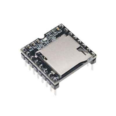
ماژول پخش فایل های صوتی DF PLAYER
۱۳۵,۰۰۰ تومان
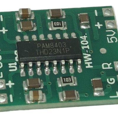
ماژول آمپلی فایر 2x3W کلاس D با تراشه PAM8403
۲۳,۰۰۰ تومان
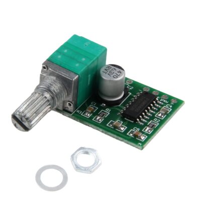
ماژول آمپلی فایر استریو 3 وات PAM8403 همراه با ولوم متغیر
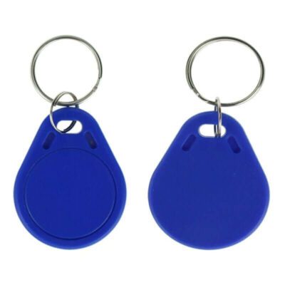
تگ RFID سر کلیدی فرکانس 13.56MHz
۲۰,۰۰۰ تومان
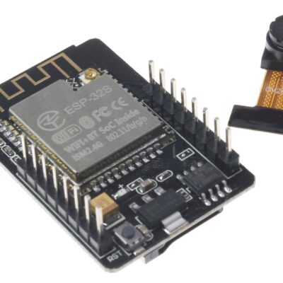
ماژول وای فای و بلوتوث ESP32-CAM
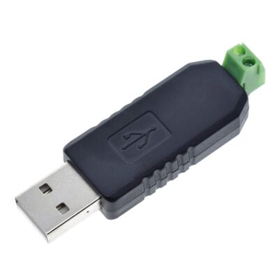
مبدل USB به سریال RS485
۱۱۵,۰۰۰ تومان


دیدگاهها
هیچ دیدگاهی برای این محصول نوشته نشده است.