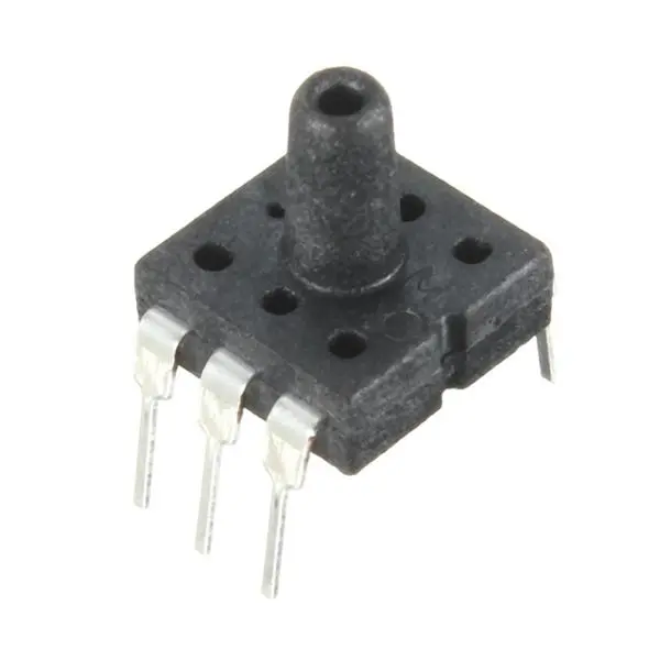
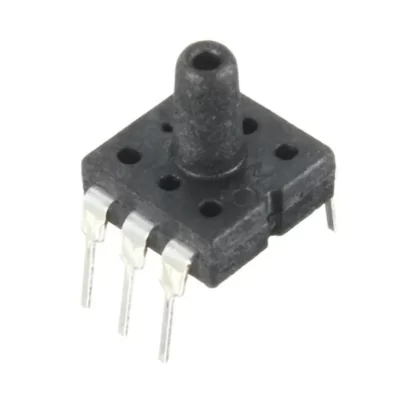
سنسور اندازه گیری فشار خون MPS20N0040D
۸۲,۰۰۰ تومان
موجود در انبار
DIP air pressure sensor 0-40kPa DIP-6
Functionality
– This DIP air pressure sensor is suitable for biomedical, meteorological and other fields.
The middle part is a pressure sensor chip made by MEMS pressure technology.
– With a wide applicable temperature range.
– Easy to use and install.
– Suitable for the following types:
1. Automotive: Tire pressure gauge, vehicle mounted air pump, MAP sensors, diagnostic equipment, automotive sensors.
2. Industry: air brake switch, portable pressure gauge, such as digital pressure gauge, environment monitor.
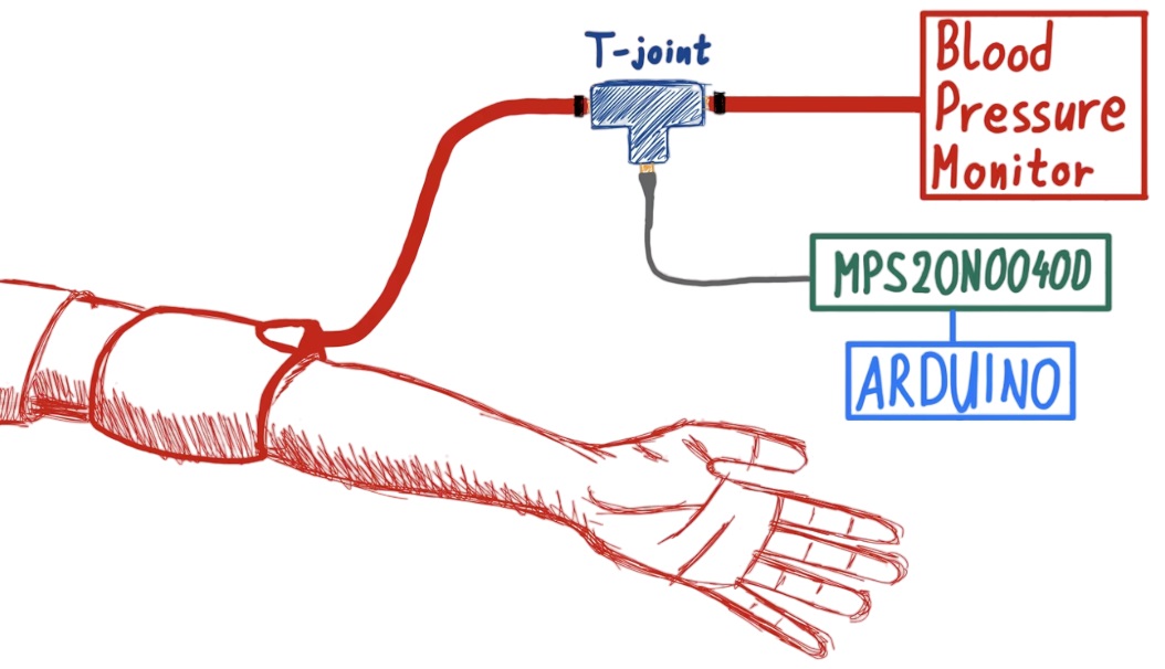
3. Medical Equipment: Patient monitoring and diagnostic equipment, such as blood pressure monitor, medical instrument and monitor.
Specification
– Measuring medium: air
– Measuring range: 0-40kPa
– Operating temperature range: -40 ~ + 125 ℃
– Storage temperature: -40 ~ + 150 ℃
– Humidity: (50% ± 10%) RH
– Ambient temperature: (25 ± 1) ℃
– Average temperature: (25 ± 1) ℃
– Output impedance: 4kΩ ~ 6kΩ
– Zero output: -15mV ~ + 15mV
– Hysteresis: + -0.7% FS
– Power supply: ≤10V DC or ≤2.0mA DC
– Insulation resistance: 100MΩ, 100VDC
Package Included
1 x DIP air pressure sensor
Experimental Setup
The manometer and MPS20N0040D sensor will be connected via an air pressure tubing configuration, where a tee junction will be used so that different pressures can be applied.
It is also recommended that either a valve or syringe is used to keep the pressure consistent during measurements.
A simple air pressure connection diagram with all the components is shown below:
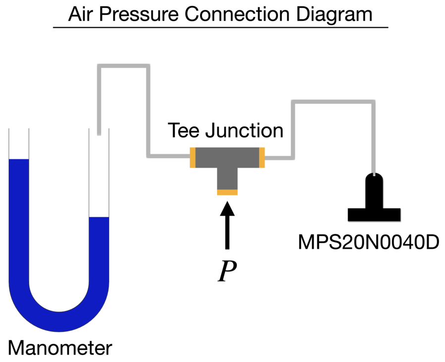
The incident pressure P, can be any application of pressure:
a bicycle pump, breath from lungs, a syringe, electronic air pump, etc.
the method of increasing and decreasing the air pressure in the tee junction is not important.
The main requirement is that the pressure must be static enough to measure consistent and stable measurements both at the manometer’s column height and the transducer’s digital signal.
MPS20N0040D Transducer Calibration
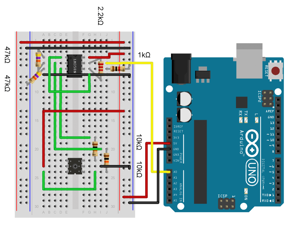
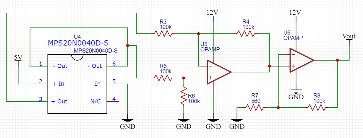
The MPS20N0040D pressure sensor should be wired to the Arduino board and connected to the tee junction tubing.
The manometer should also be connected to the tee junction.
And finally, the chosen method of pressure application should be connected to the last input at the tee junction.
The method of calibration involves varying the pressure input to change the height of the water column in the U-tube manometer.
This will allow us to record measurements of the manometer (a caliper is an accurate measurement of column height), and use those pressure measurements to fit the voltage response of the MPS20N0040D.



دیدگاهها
هیچ دیدگاهی برای این محصول نوشته نشده است.